Custom P&ID drawing software that supports real engineering workflows

Discover how custom P&ID software supports real engineering workflows and why standard CAD tools fall short in complex projects.
P&ID drawing software helps engineers work faster and with fewer errors than standard CAD with plug-ins. By reducing manual redrawing and supporting real-time collaboration, teams can prepare better offers, avoid rework, and deliver projects with more confidence – without changing proven engineering workflows.
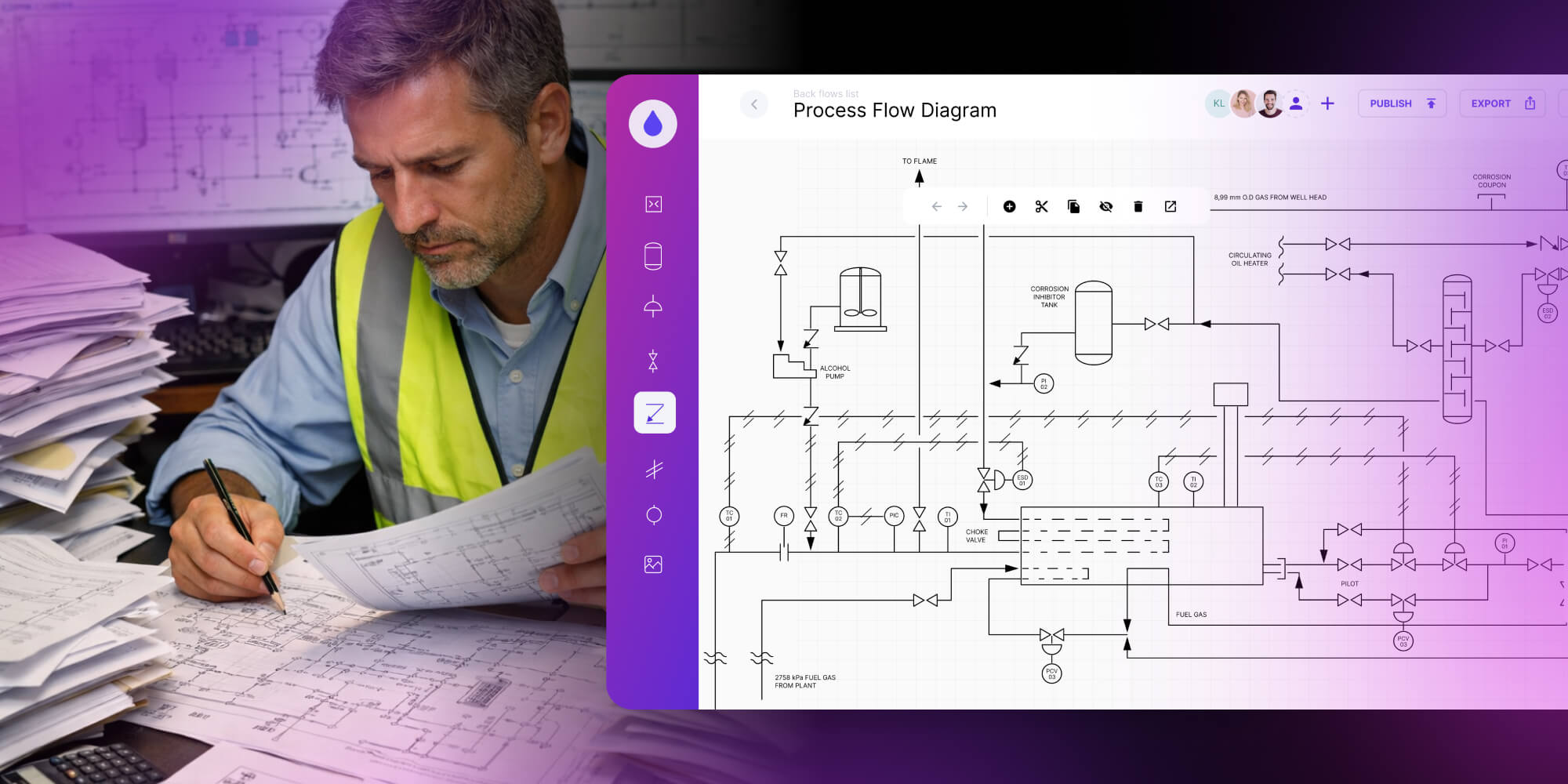
2D CAD drawings sit at the center of many industrial projects, yet the way they are created has barely changed for years. In most engineering organizations, like piping and instrumentation, diagrams are still produced using general-purpose CAD tools that were never designed specifically for P&ID work. As a result, one of the most critical engineering artifacts is also one of the most time-consuming and error-prone.
This article focuses on how custom P&ID drawing software can support real engineering work – by removing friction that has been accepted as “part of the job.”
Transform your technical drawing workflow and go 10× faster
Learn more.png)
P&ID drawings remain one of the most labor-intensive engineering deliverables
From an engineering perspective, creating a P&ID diagram is not conceptually difficult. The challenge lies in execution. Symbols, connections, tags, and annotations must all remain consistent as the project evolves. Every revision introduces the risk of breaking that consistency.
In practice, engineers spend a disproportionate amount of time on mechanical tasks:
- placing and aligning symbols by hand,
- manually drawing and redrawing connections,
- updating tags and labels after every change,
- checking and making revisions.
These tasks are usually performed in standard CAD environments. While CAD tools are powerful, they treat P&ID drawings as static geometry, not as evolving process documentation.
The hidden cost of this approach is time. Engineers often lose hours every week to repetitive drafting work that could be handled more efficiently with better tooling. If you want to see how these manual workflows translate into real financial losses, this article breaks it down clearly: What is CAD automation – and how much do you lose due to repetitive, manual tasks?
Why general CAD tools struggle with P&ID drawings?
Most engineers create P and ID drawings using general CAD software with add-ons. These tools are flexible, but they were never built to understand process logic, engineering constraints, or industry-specific rules.
Drafting tools don’t understand process logic
Generic CAD tools allow almost any connection, symbol placement, or tag combination. From a drafting perspective, this is freedom. From an engineering perspective, it is risk. The software does not distinguish between valid and invalid configurations.
As a result:
- incorrect connections are easy to create,
- errors surface late, often during reviews,
- validation depends entirely on manual checks.
This is the fundamental difference between CAD and purpose-built P&ID diagram software. P&ID work follows rules, standards, and dependencies that CAD alone simply do not enforce.
Collaboration and revisions amplify the problem
P&ID drawings rarely belong to a single person. Designers, reviewers, safety engineers, and project managers all work with the same diagrams. In traditional setups, this often leads to duplicated files, version conflicts, and slow feedback loops.
When P and ID diagrams become part of the sales or delivery process, these delays grow even more painful. If drawings are required to prepare offers or technical proposals, manual workflows directly slow down business decisions.
What supporting engineering work actually means?
Supporting engineering work does not mean fully automating P&ID creation. It means recognizing that engineers already understand the process – and giving them tools that stop getting in the way.
Well-designed P&ID drawing software supports engineers by:
- reducing repetitive manual actions,
- guiding valid connections and configurations,
- making errors visible while the diagram is being built,
- keeping the interface familiar and predictable,
- allowing many specialists to work simultaneously.
This is where P&ID automation plays a role. Automation handles repeatable mechanics and consistency checks, while engineers remain responsible for design decisions, safety assumptions, and logic.
Custom tools built specifically for P&ID workflows make this possible.
From static drawings to living custom P&ID software
For decades, P&ID drawings have been treated as static documentation. Once approved, they were archived as PDFs or CAD files and revisited only when something broke or a major change was required. That model no longer reflects how modern engineering organizations operate.
Today, a P and ID diagram is expected to support far more than initial design. It must evolve with the project, remain usable, and provide context for decisions long after commissioning.
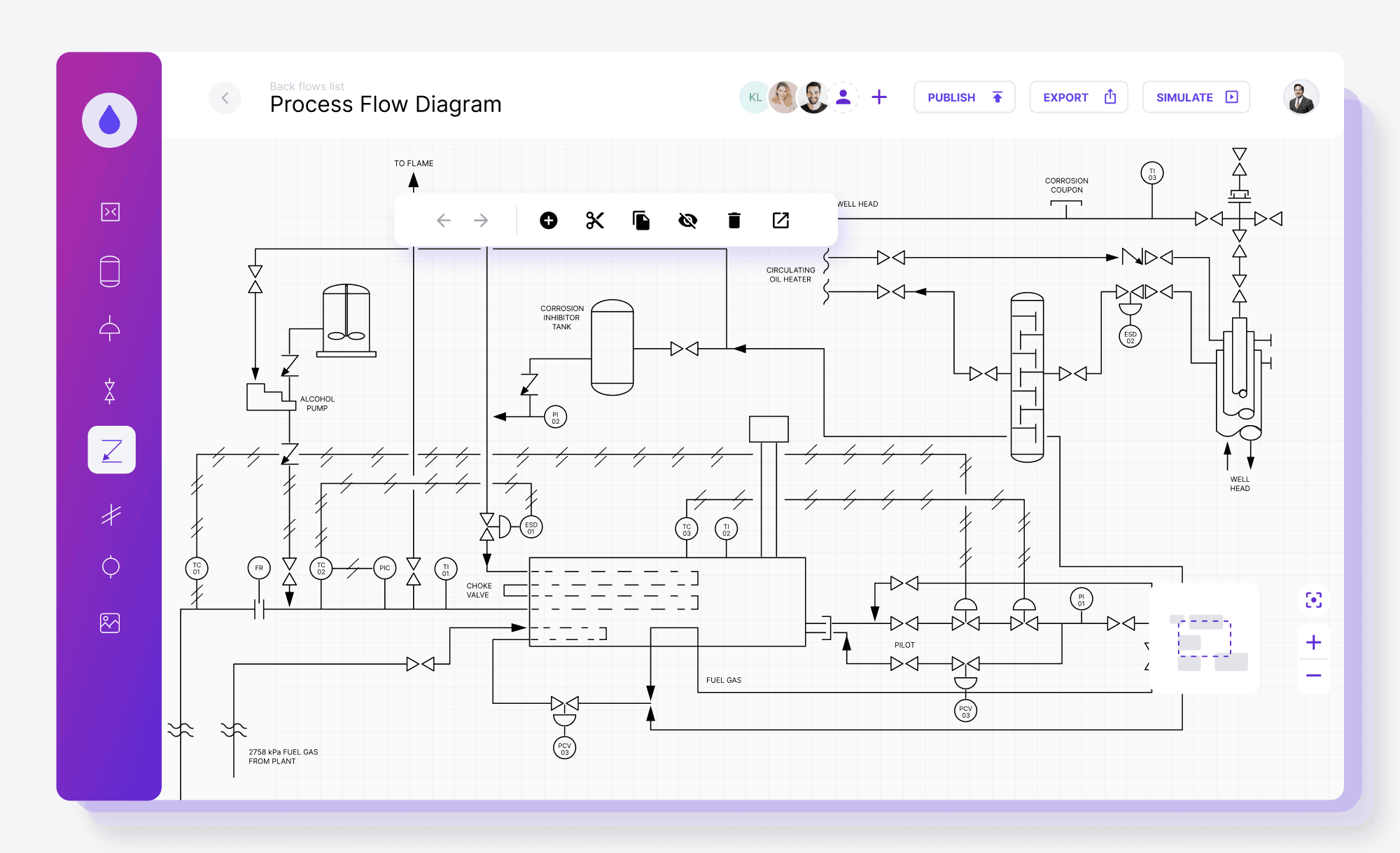
Modern P&ID diagram software treats diagrams as living assets rather than frozen – paper or digital – drawings.
Instead of asking engineers to manually synchronize data, revisions, and annotations, the software keeps relationships intact as changes occur. A valve replacement, a parameter update, or a safety-related modification no longer requires a cascade of manual corrections across multiple files. The diagram updates as part of the workflow, not as an afterthought.
For a deeper dive, check Ultimate guide to piping and instrumentation diagram software or take a look at our case studies below.
Real-time digital twin thanks to custom P&ID software
Anyone who has worked on large P&ID projects knows the unspoken assumption: everyone hopes they are looking at the latest version. In reality, drawings are copied, annotated, emailed, and revised in parallel, making it hard to know which version reflects the real system.
This was a challenge for our client from the oil and gas industry. Engineers and operators needed to work on the same P&ID diagram at the same time, without losing trust in the documentation.
We addressed this by building a custom P&ID drawing software that functions as a digital twin of the refinery’s piping and instrumentation network. Instead of managing files, teams worked on a shared, live diagram representing the actual system.
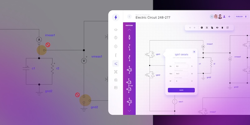
The solution combined several domain-specific capabilities:
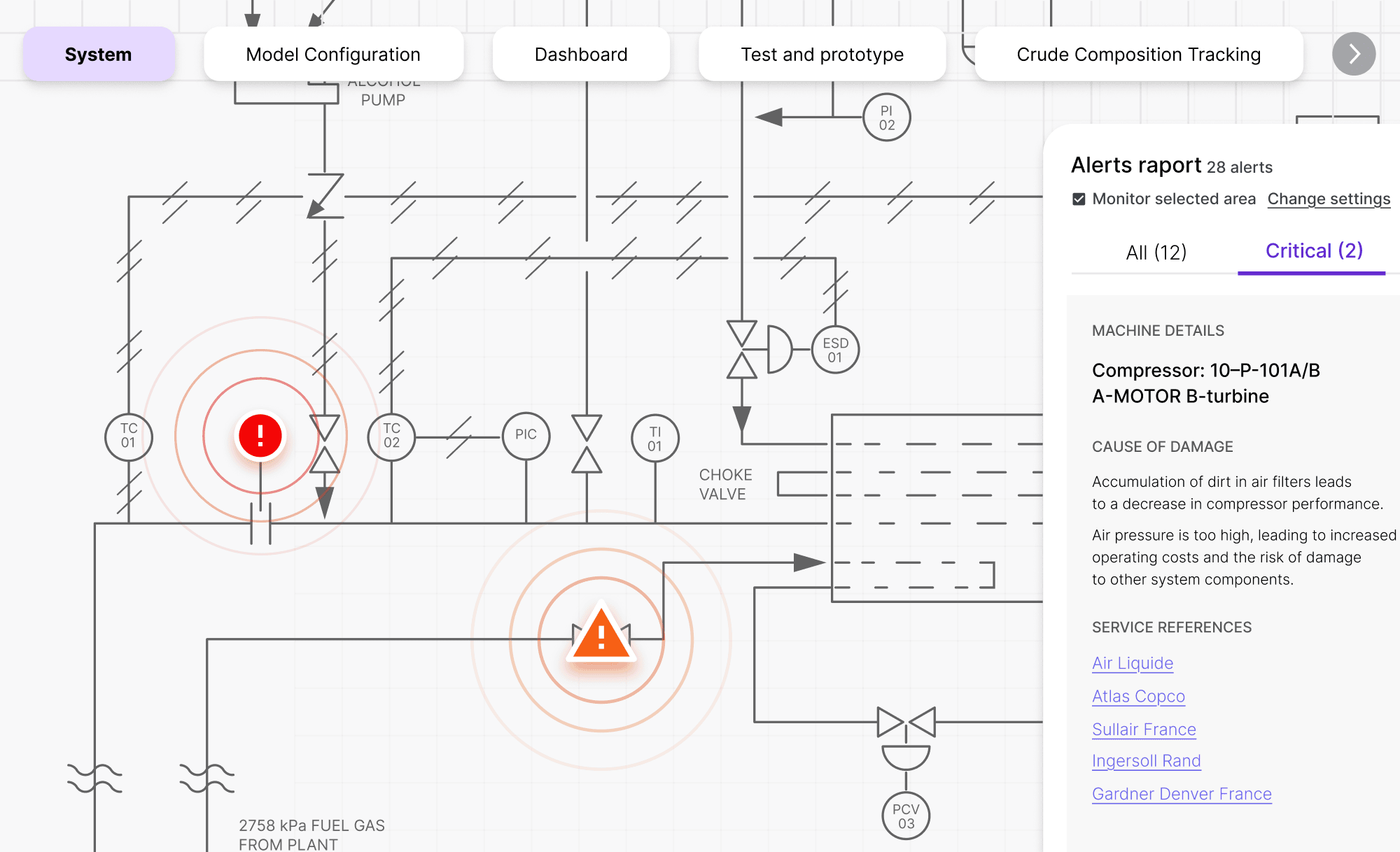
- Digital twin simulation – live and animated flow visualization to understand system behavior and test failure scenarios.
- Guided diagram creation – auto-completion and snap-to-grid to ensure valid connections.
- Real-time validation – multi-level warnings (concern, warning, error) highlighting potential risks directly on the diagram.
- Collaborative editing – multiple users working on the same P&ID with immediate visibility of changes.
→ The full case study: Improving Effectiveness with P&ID Software.
Collaborative P and ID software with sandbox mode and data tracking
In projects for the energy and petroleum company, custom P&ID automation is not about redefining engineering work. It is about supporting specialists in environments where complexity, safety, and scale really matter.
In the refinery case, the custom software handled repetitive and error-prone mechanics, while engineers remained fully responsible for process logic and design decisions.
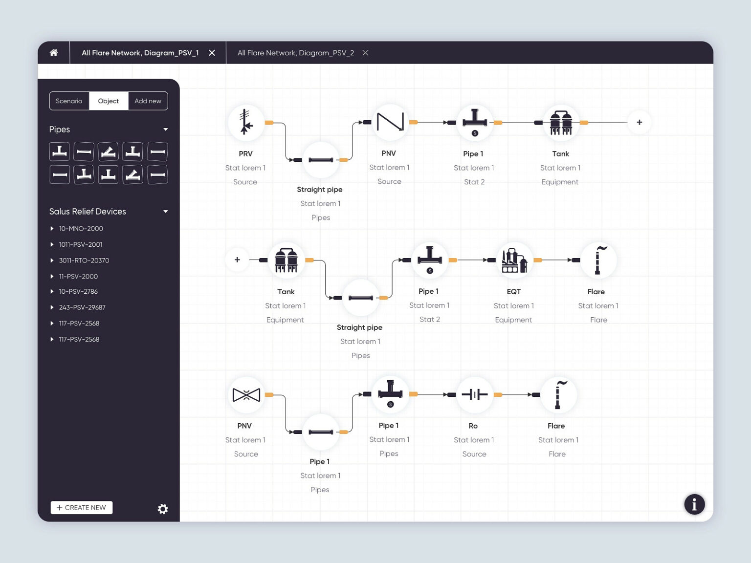
The solution introduced:
- Auto-completion and guided connections to ensure valid piping and instrumentation layouts,
- Sandbox mode within the P&ID diagram software, allowing users to experiment using actual data without altering the operational system.
- Integrated monitoring and trend analysis to connect diagrams with operational data.
→ The full case study: Gain real-time operational insight with a custom piping and instrumentation diagram software.
Automation of technical drawings for P&ID
Modern engineering software can do more than speed up manual diagram work. It can automatically generate technical drawings from structured data and predefined rules.
First, the custom system is configured around clear engineering logic – rules, relationships, and constraints. Next, the team provides structured input data. Based on that logic and data, the tool generates a piping layout automatically. Engineers can review, validate, and edit the diagram if needed. The main win is that the most time-consuming step – drafting – is handled automatically, saving hours of specialist work.
Traditional P&ID drawing processes are time-consuming and tool-heavy. It often requires multiple manual tools and handoffs. Automation is changing this process.
- A custom tool for diagram automation can be built as flexible, component-based software, tailored to specific businesses and processes.
- Data table input – structured information is fed into the system, typically as an Excel table.
- Data-to-diagram conversion – the tool applies predefined logic to generate a complete layout, ready for review and small, detailed edits.
Why algorithmic automation works better than AI for P&ID?
P&ID requires strict rules and repeatable precision. Current AI models still struggle with reliable technical diagram creation, and there are no scalable, production-ready AI solutions widely used for demanding P&ID environments.
That’s why Synergy Codes’ solution relies on algorithm-based methods to convert data into diagrams with predictable layout, connections, and validation behavior.
Custom P&ID drawing software vs. standard CAD tools
Where P&ID automation helps experienced engineers work better
Custom P&ID automation is often misunderstood as an attempt to “do the engineer’s job.” In reality, the opposite is true. No software can replace the experience required to design, review, and validate complex industrial processes.
What custom P&ID design software can do is remove the friction that has built up around that work.
In our projects, automation focuses on mechanics that slow engineers down:
- repetitive placement of symbols,
- enforcing valid connections,
- maintaining consistency across revisions, and flagging issues early.
These are tasks that don’t require creativity or judgment, but consume a surprising amount of time.
This is not about radical change or unfamiliar tools. It’s about building software that feels intuitive, familiar, and trustworthy – a focused “slice” of CAD that fits naturally into existing workflows instead of fighting them.
With Synergy Codes’ custom P&ID software, the engineer remains fully in control. The software simply supports that work by making it faster, clearer, and less error-prone. Over time, this builds confidence not only in the tool, but in the diagrams themselves.
Keep manual control of P&ID diagrams and automate repetitive technical drawing tasks
Check the offer
Why custom P&ID software improves speed, quality, and delivery confidence
For technical managers, P and ID drawings are not just engineering documentation. They directly affect how fast your team can prepare offers, how reliable those offers are. As project volume grows, manual workflows stop scaling. More projects mean more drawings, more reviews, and more coordination overhead. Custom P&ID automation removes repetitive work from the process, allowing engineering teams to handle higher volume without increases in effort.
With custom P&ID software, teams gain:
- Faster quoting cycles – diagrams are generated and validated quicker, so offers go out sooner.
- Higher offer quality – consistent, readable P&ID diagrams reduce misunderstandings across teams and clients.
- Lower delivery risk – fewer late-stage corrections caused by documentation issues.
- Better engineering focus – engineers spend time reviewing and validating, not redrawing.
If P and ID diagram slow down your sales process or create uncertainty in offers, the problem is rarely the team. It’s usually the tools they’re forced to work with. Custom P&ID CAD software aligns engineering workflows with business goals – and that’s where the real value lies.
Final thoughts
Custom P&ID drawing software is not a shortcut. It is a strategic investment in how engineering knowledge is created, shared, and maintained over time.
For organizations operating at scale, with complex systems and high safety requirements, relying solely on generic CAD tools eventually becomes a constraint. Purpose-built P&ID software removes that constraint by supporting real workflows instead of fighting them.
If your P&ID diagrams are becoming harder to manage, trust, or scale, it may be time to rethink not how your engineers work – but how your tools support them.
- How is custom P and ID drawing software different from standard CAD tools?
P and ID drawing software is built around process logic and engineering rules, not just geometry. Unlike standard CAD, it helps maintain consistency, guides valid connections, and reduces errors during revisions of P and ID drawings.
- Why do teams move beyond P&ID CAD as projects grow?
In small projects, P&ID CAD can work – one engineer owns the file, changes are limited, and manual checks are manageable. But as scope grows, drawings become living documents shared across disciplines. Revisions pile up, parallel edits create version confusion, and reviews turn into time-consuming audits. Purpose-built P&ID design software reduces this friction by enforcing standards, guiding valid connections, and making changes easier to track and trust.
- Does P&ID design software replace experienced engineers?
No. P&ID design software supports engineers by reducing repetitive drafting work. Engineers still make all design and decisions – the software simply helps them work faster and with fewer mistakes.
- When should a company consider custom P and ID software?
Custom P and ID software makes sense when manual workflows slow down sales, revisions are hard to control, or P and ID drawings are reused across many projects. At that point, better tools reduce risk and improve scalability.
- Which tool can be used to build a custom P&ID diagram editor?
A good example is ngDiagram – an Angular-based diagramming library designed for building custom, interactive diagram editors. It gives teams full control over nodes, connections and validation logic, making it well suited even for engineering-grade P&ID workflows.
UX and Product Designer blending artistic vision with technical expertise and a research-driven mindset. Łukasz designs inclusive, accessible digital products where aesthetics meet functionality. He is passionate about cognitive psychology and how accessibility shapes user experience. In his work, he combines empathy, behavioral analysis, and attention to detail to create interfaces that support diverse user needs.

Find how we can help you enhance your software and win more deals
Contact us to discuss your project. After you submit the form, we’ll get in touch with you within 48 hours to arrange a call.