When standard electrical CAD tools aren't enough: the case for custom automation

Standard electrical CAD handles drawings, but not the workflow around them. Learn when custom automation becomes the more practical path for engineering teams.

Electrical CAD tools handle many drawing-level tasks well, but they become harder to scale when teams need integration, custom validation, and automatic updates across the whole project. At that point, the cost of manual updates, workarounds, and disconnected data becomes harder to control.
When standard electrical CAD tools aren’t enough: the case for custom automation
There’s nothing wrong with electrical CAD. Tools such as AutoCAD Electrical, EPLAN, and SOLIDWORKS Electrical have earned their place on engineering teams worldwide. They’re powerful, feature-rich, and for many projects, they get the job done.
But if you’ve ever spent a week updating wiring diagrams after a single specification change, or watched a senior electrical design engineer work their afternoon reconciling documentation across tools after a mid-project revision, you already know where the cracks are.
Standard electrical CAD was built to help engineers draw, not to automate how they work. And as projects scale, that gap gets expensive.
This article examines where these tools fall short, what that means for your team, and when custom automation becomes the smarter path.
See how custom electrical design software works for your team
Book a consultation.png)
Where standard electrical CAD reaches its limits
Electrical drawing still requires manual work across the project
Modern electrical CAD tools automate many individual tasks and handle wire numbering, component tagging, report generation, and PLC I/O drawing creation effectively.
What still relies on manual work is the project as a whole.
Engineers place components, define connections, and build each schematic separately. When a specification changes – a component type, voltage level, or signal definition – that change has to be applied across multiple outputs:
- Schematics
- Cable schedules
- Terminal plans
- Control panel layouts
Reports can regenerate, but consistency still depends on manual checks. Miss one update, and it shows up during commissioning, with on-site fixes and delays.
Standard electrical CAD tools come with fixed workflows
Electrical CAD tools are built around predefined workflows. They assume a certain way of structuring drawings, naming elements, and organizing documentation, including limited support for complex 3D workflows or non-standard project structures.
For teams working with internal standards, client-specific requirements, or regulated environments (IEC, IEEE, ANSI, NEC), this creates problems:
- Naming conventions that don’t match internal standards,
- Approval steps handled outside the tool,
- Manual review cycles to catch inconsistencies.
Automation exists, but only within the logic defined by the software. Generating outputs like panel layouts or cable schedules is possible, but only if the project fits the expected structure. If it doesn’t, teams rely on exports, manual edits, or custom macros, all of which are difficult to maintain.
Data is spread across multiple systems
In most projects, key data stays in separate tools – component specifications in vendor databases, drawings in electrical CAD, pricing in ERP, documentation in shared folders. This separation makes it difficult to maintain consistent information across the project.
Version control adds another layer of difficulty. In many teams, tracking changes still depends on file naming conventions and manual documentation. When multiple engineers work on the same project, identifying the current version and understanding what changed between revisions often requires comparing files side by side.
Scaling teams isn’t straightforward
Electrical CAD tools have a steep learning curve. Much of the process knowledge isn’t documented in the tool itself but is held by experienced engineers who know how to avoid common errors, apply conventions correctly, and handle edge cases in large projects.
New engineers need time to learn internal standards and the structure of designs. Until then, productivity depends on a small group of experienced people. When those engineers leave, that knowledge leaves with them.
Over time, these issues start to stack up.
When custom automation becomes the practical next step
Not every engineering team needs a custom-built platform. Standard electrical CAD works well with predictable project types and limited integration requirements. But you can tell when the tool starts creating extra work instead of saving time.
Your workflows don’t fit the tool
An engineer designing industrial control systems for a pharmaceutical plant works under different rules than someone building power distribution for a data center. Standard tools don’t account for that.
You start to see it in how the team works:
- Teams keep separate documentation outside the tool
- Engineers use custom macros or scripts to fill missing functionality
- Designs go through manual review cycles to catch inconsistencies
- Data is moved between systems that don’t share information
Over time, these workarounds add up. Each extra step slows things down and introduces points where something can go wrong.
Most teams that come to us aren’t looking to replace CAD. They’ve hit a point where their tool handles drawings well, but can’t keep up with the workflow around them – integration, validation, change management. That’s where custom automation starts making sense.
You need systems to talk to each other
When electrical CAD is not connected to other systems, engineers end up moving data manually between tools and spreadsheets. In larger projects, that often means entering the same information in multiple places:
- ERP and procurement platforms
- SCADA systems and operational databases
- Component vendor libraries
- Project documentation and asset management tools
A connected platform removes that step. Data flows between systems instead of being copied across them.
Validation can’t depend on manual review alone
In projects with hundreds of connections and components, every wire number, rating, and safety parameter must be verified. Across wiring diagrams and control panel designs, this turns into a large amount of detailed checking work. When errors appear late in the project, teams spend extra time tracing issues back and correcting them across multiple outputs.
With rule-based validation, every change is checked as it is made. If something doesn’t match the defined rules, it shows up right away.
Custom automation lets you use your own rules – company standards, client requirements, or compliance constraints – rather than being limited to what the electrical design software covers.
When speed starts to cost you
Tight timelines and growing backlogs put pressure on teams to deliver more without additional resources.
Building each part of the design separately takes time. With multiple projects running in parallel, that overhead adds up quickly and increases the risk of inconsistencies and missed updates.

What changes when we build around the process, not the tool
We’ve worked on projects where these issues had a direct impact on delivery. The examples below show how teams addressed them by building tools around their own processes and systems.
Replacing an off-the-shelf tool that couldn’t keep up
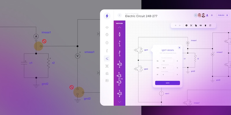
OPAL-RT Technologies builds real-time simulation systems for automotive, aerospace, power electronics, and energy industries. Their engineers model electrical circuits before running Hardware-in-the-Loop tests, but the market tool they relied on was not sufficient. It lacked the functionality they needed, didn’t connect to their simulation environment, and came with licensing costs that were hard to justify.
We built a custom schematic editor that changed how their team works:
- Engineers assemble circuit models in a drag-and-drop editor with built-in validation,
- Models are stored in a database and reused across projects,
- The tool connects directly to OPAL-RT’s HYPERSIM and RT-LAB environments, linking design with simulation.
The first working prototype was delivered in four weeks.
Turning P&ID diagrams into a working layer of the system
A multinational petroleum company needed a more effective tool to visualize refinery schemes and improve its process-monitoring capabilities. Standard market solutions didn’t offer the functionality they required.
We built a platform that connected diagrams directly with operations:
- Sensor data appears directly on the schematic, with real-time alerts,
- Multiple engineers can work on the same diagram at the same time thanks to concurrent editing,
- A sandbox environment allows teams to test changes using real operational data.
The platform integrates with the company’s existing systems, so there was no need to replace their infrastructure.
What these projects had in common
In both cases, the starting point was a tool that handled electrical drawings but didn’t support the full workflow. Design, simulation, operations, and collaboration were split across separate systems.
Custom automation connected these parts into a single environment, where data is shared, and changes don’t have to be repeated across tools.
The biggest time savings usually come from eliminating the work between tools – the manual re-entry, the version checks, and the reconciliation. Once that’s automated, engineers get back to designing.
Standard electrical CAD vs. custom automation
Standard electrical CADCustom automation platformWorkflowConfigurable, tool-defined templatesBuilt around your team’s process and toolchainTask automationWire numbering, tagging, reports, macrosEnd-to-end project automation: drawings, docs, validationData validationBuilt-in checks; many rules checked manuallyRule-based, real-time, company-specific validationIntegrationFile exchange and standard connectorsDeep links to your ERP, SCADA, and databasesOnboardingPowerful but complex; months to masterRole-based UI with a lower learning curveScalabilityHandles large projects with careful setupDesigned for large projects (e.g., 3,000+ components)Engineering collaboration toolsProject sharing via files and vendor ecosystemsConcurrent editing, versioning, and reviews on a shared modelDynamic diagramsStatic design documentation and exportsLive, data-connected schematics for monitoring and analysis
Custom automation isn’t a replacement for electrical CAD entirely – it’s a CAD alternative that fills the gaps packaged tools can’t. Many teams continue using AutoCAD Electrical or EPLAN for specific tasks. What custom automation adds is project-level workflows, cross-system integration, and workflow automation rules that align with how your company operates.
For teams evaluating whether to take this step, the question comes down to this: are your engineers spending more time managing their tools than designing systems?
Outdated electrical drawings cost teams 30% of project time.
Score your teamIs custom electrical design software the right step for your team?
If your electrical CAD workflow involves manual workarounds, disconnected systems, and late-stage error correction, the tools to change that already exist.
You’re likely ready for custom automation if:
- specification changes regularly trigger manual updates across multiple documents,
- your team maintains parallel trackers, macros, or scripts to fill gaps in the tool,
- integration between your design environment and ERP, SCADA, or procurement systems depends on manual data entry,
- onboarding new engineers takes months because the process knowledge lives with people, not in the system.
Custom automation isn’t about replacing everything at once – it starts with one bottleneck and grows from there.
Book an engineering consultation to explore what a custom-built electrical system design software platform could look like for your team.
- What is custom automation in electrical design?
Custom automation refers to purpose-built software platforms that automate project-level electrical design tasks – schematic generation, validation, documentation, and integration with enterprise systems like ERP and SCADA, going beyond the built-in features of packaged electrical CAD tools.
- When should an engineering team consider custom automation?
Common signals include reliance on manual workarounds, parallel documentation outside the tool, difficulty integrating electrical CAD with ERP or SCADA systems, and late-stage errors that could have been caught during design with automated validation.
- Can custom automation integrate with existing electrical CAD tools?
Yes. Custom platforms aren’t replacements for electrical CAD – they work alongside tools like AutoCAD Electrical or EPLAN. Integration typically includes data import/export, project synchronization, and shared component libraries.
- What industries benefit from custom electrical design software?
Any industry with complex electrical systems – energy, oil and gas, manufacturing, automotive, aerospace, and power electronics. The benefits are strongest for teams managing large-scale projects, multi-site operations, or strict compliance requirements.
- How long does it take to build a custom electrical design platform?
Timelines vary by scope, but working prototypes can be delivered quickly – the OPAL-RT project described in this article had its first working prototype ready in four weeks. The full platform grows incrementally from there.
- Can Synergy Codes build a custom automation platform around our existing CAD workflow?
Yes. Synergy Codes builds purpose-built electrical design software tailored to your processes, standards, and enterprise integrations. Explore the offering.
A Content Marketing Specialist with 6 years of IT industry expertise, crafting everything from in-depth ebooks to strategic brand narratives. Weronika understands diverse tech audiences and ensures every piece delivers value in the most accessible way possible.

Find how we can help you enhance your software and win more deals
Contact us to discuss your project. After you submit the form, we’ll get in touch with you within 48 hours to arrange a call.