Custom electrical schematic configurator: step-by-step implementation guide

Off-the-shelf electrical design software stops scaling when workflows become complex. A custom configurator removes the bottlenecks.

Based on 3 real-world implementations in energy, simulation, and infrastructure engineering, this article shows how custom electrical schematic configurators replace multistep update processes with real-time, self-service workflows. They remove developer dependency, reduce errors with built-in validation, and create a unified system where engineers can work directly on electrical diagrams.
This article is for engineering teams and decision-makers working with an electrical system design software who are starting to see the limits of standard tools – especially when building complex products. It explains how a custom electrical schematic configurator can change that dynamic, moving from request-based workflows to real-time, self-service diagram configuration.
From this guide you'll learn what actually happens when a company replaces fragmented tools with a custom-built solution – not in theory, but through outcomes based on real-world projects.
The reality behind most electrical system design software
Most teams don't question their electrical system design software until everyday tasks start taking longer than they should. What begins as a manageable workflow gradually turns into a chain of dependencies between engineers, developers, and release cycles.
Starting point – every schematic update is a formal process
In many organizations, updating an electrical drawing is not an engineering task. It is a process that moves through multiple roles and systems before anything changes in production:
- Engineer submits a request,
- Developer implements the change,
- QA verifies it,
- Release cycle pushes it to production.
This creates a situation where engineers are technically responsible for system design, but operationally blocked from making changes. Even something as small as modifying a symbol in a wiring diagram can take hours or days.
Move beyond generic electrical design software
Get custom editor.png)
The other extreme: when standards don't exist
While most organizations struggle with formal processes, some teams face an opposite problem – they lack any standardized process at all. In these cases, device lists, equipment configurations, and naming conventions vary by engineer. Each person has their own approach.
In one of our industrial projects, this became clear immediately. The device and equipment list were not standardized – each engineer created them differently. This created friction even for us during system design. Working through this challenge together, the client and our team established a standard that engineers now propagate to their teams through the custom system itself.
It's not a tooling problem. It's a structural problem.
Off-the-shelf design software works well as long as workflows remain generic. It supports drawing, documentation, but once systems become more complex the limitations start to surface.

The problems begin when:
- Diagrams must reflect real devices and simulation logic,
- Control logic visualization must match standards,
- Systems need to scale across thousands of components,
- Every change must stay consistent across tools.
In this case a custom electrical schematic configurator is not a luxury – it is a business response to a structural limitation of standard software.
Enterprise teams don't move to custom solutions because they want more features. They do it because their workflows no longer fit inside generic tools.
How custom solutions address real business constraints?
Every project starts at the same pain point – when updating electrical diagrams becomes a bottleneck instead of a task.
This guide walks you step by step through the implementation of electrical system design software, showing where a custom approach removes specific operational bottlenecks and replaces them with scalable, engineer-driven workflows.
Discovery phase – identifying the real problems
Most teams approach software with a feature mindset. They look for missing capabilities in their current tools and assume that adding them will fix the workflow. In practice, that assumption breaks down fast.

What did the discovery phase actually reveal?
During discovery, the focus shifts from "what features are missing" to "how the system behaves as a whole."
At this stage, Synergy Codes works closely with the client through needs analysis, workshops, and mapping of existing workflows. The goal is not just to capture requirements, but to identify the real problem behind them – not only its symptoms.
It helps to determine what the project actually requires at its core.
Building around the real bottleneck
By the time any design starts, the core problem should be clear. The question is no longer whether a company needs better diagrams. The real question is what keeps those diagrams from being useful in daily work.
- In one class of projects, the issue is that engineers can draw a system, but the drawing is disconnected from simulation logic.
- In another, the challenge is speed – the diagram has to reflect live readings and incidents almost immediately.
- In another example, the bottleneck is layout: the client already has the data, but turning it into a readable, standards-compliant diagram is still too slow or too manual.
These are different business problems, but they all push companies toward the same conclusion: generic electrical system design software is not enough.
Real-life case studies
This is why all work has to start from the operational pain.
In the OPAL-RT case engineers were already using a market-available tool – Simulink. However, the solution turned out to be insufficient for their needs due to limited flexibility. This tool was too generic for a simulation environment in which every object had to represent a real device with supported properties, and every change needed validation against backend rules. That required a system where frontend and backend validation worked together, and where user actions could be reflected in the system immediately.
For a client in the energy sector, the challenge went beyond building diagrams. The interface had to display real-time readings and system states directly on top of the diagram, fast enough to support operational decisions. The real value came from combining visualization of electrical flow with live data – for teams looking for SCADA alternatives, this kind of solution turns static diagrams into active monitoring tools, not just a static representation.
In another project for an engineering company, the bottleneck was readability at scale. The client could import data about devices, properties, and connections, but still needed that data turned into a clear technical diagram that matched specific electrical layout expectations. The real problem was how to generate a readable result under custom constraints.
From symptoms to system-level decisions
Discovery phase can translate business pain into technical requirements:
That's why the discovery stage is so important. By talking with the client and understanding their current workflow and needs, you can approach design phase with specific pain points in mind.
Design phase – shaping electrical system design software around real user behavior

Design is where concepts meet reality.
At this stage, custom software starts taking the form of an actual tool which will be used by engineers, operators, or analysts. The goal is not to make it only "look good." The goal is to make it usable in the context of real workflows, constraints, and expectations.
Defining roles, modes, and real usage scenarios
One of the most common mistakes in design is treating all users the same. In practice, different roles interact with the system in very different ways.
Key questions at this stage include:
- Who creates and edits diagrams, and who only reviews them,
- What actions are allowed in edit mode vs. read-only mode,
- Whether the system is used on PCs or standard laptops.
Designing without this distinction leads to cluttered interfaces or restricted workflows.
Aligning with industry standards and expectations
Unlike generic diagram tools, electrical system design software must follow domain-specific conventions.
Users expect diagrams to:
- Follow established visual standards,
- Remain readable even with hundreds of elements,
- Reflect familiar patterns from CAD tools.
If the system breaks these expectations, adoption drops – even if the tool is technically more advanced. Design, in this context, is not about innovation for its own sake. It is about consistency with how engineers already think and work.
Prototyping and validating with users
Mockups and prototypes are the first working versions of the system – not yet final, but detailed enough to simulate real interactions. They allow teams to see how the electrical system design software will actually behave before development begins. Their role is simple: to test decisions early, when changes are still fast and inexpensive.
At this stage, teams test:
- Whether interactions feel natural,
- Whether users can complete key tasks without friction,
- Whether the system supports real workflows, not just ideal ones.
This often reveals gaps that are not visible during discovery. For example:
- Users may expect faster ways to reuse components,
- Certain actions may require fewer steps,
- Visual hierarchy may not match how users scan diagrams.
This is also the moment when functional logic turns into a complete interface. UX decisions are translated into a visual structure that reflects how the system should work in practice. These insights directly shape the final behavior of the system.
Designing interaction logic – where complexity hides
In the OPAL-RT case, this became clear early in the process.
The design had to support highly specific connection behaviors, including:
- Branching from any point on a link,
- Showing unfinished connections as dashed lines,
- Automatically merging lines during movement,
- Keeping connections straight and readable when elements are moved.
These are not visual details. They define how users think about and manipulate the system. If these interactions feel wrong, the tool becomes frustrating regardless of its capabilities.
This is also a good example of how the solution was shaped in practice. These behaviors were not predefined features, but responses to how OPAL-RT engineers actually worked. Synergy Codes translated those expectations into system logic, ensuring the tool matched real usage instead of forcing users to adapt.
Design decisions that impact development later
Many technical challenges originate in design decisions. That is why design and development cannot be separated. Poor design assumptions lead directly to complex or inefficient implementations.
Development phase – where the system starts working in real conditions
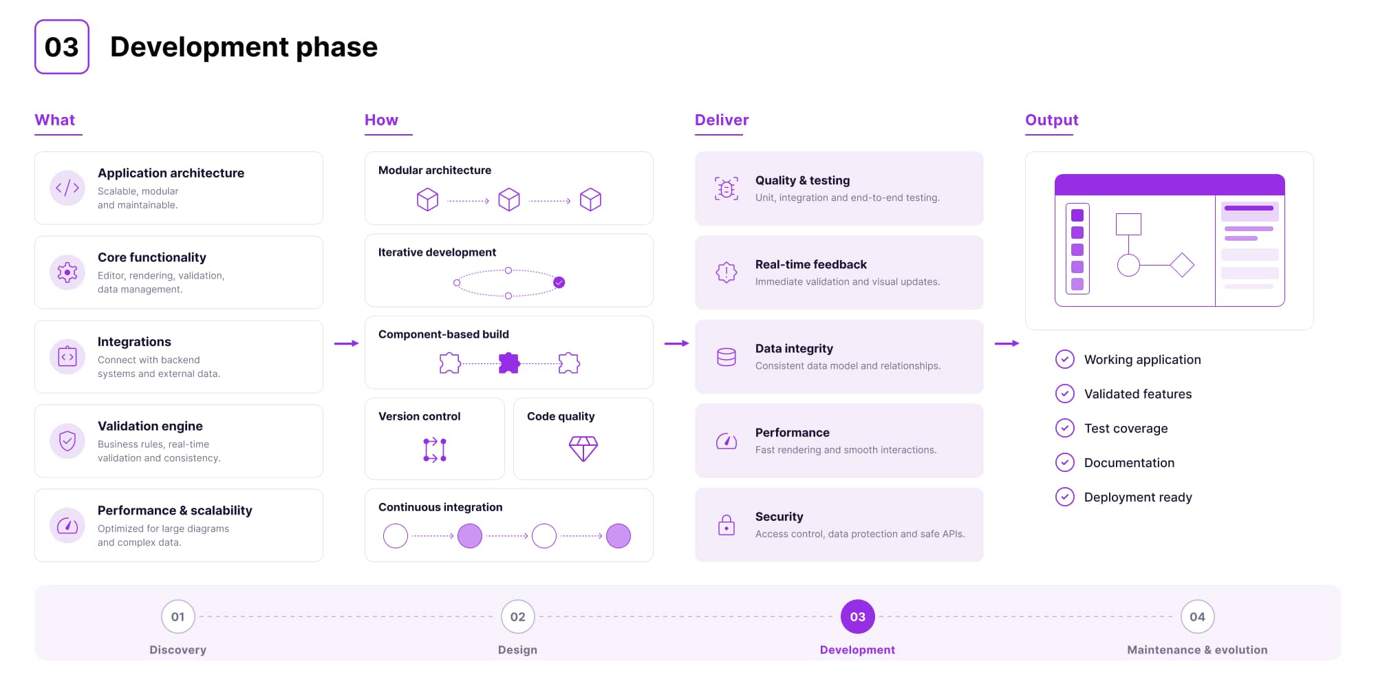
Once the direction is clear, development begins. This is where architecture is chosen, libraries are selected, and the first working versions of the system are built.
Flexible model of collaboration
At Synergy Codes, this stage is always tailored to the client. In some projects, the team delivers the full solution, including both frontend and backend. In others, it focuses on the frontend layer and diagram logic, integrating with the client's existing systems.
The OPAL-RT project is a clear example of this approach. For the first six months, Synergy Codes also built the backend. Later – once the client decided to take ownership of that layer – it was handed over to their internal team of over 200 engineers. The frontend and diagram logic remained part of the collaboration. This matters because it shows that a custom solution does not limit future decisions. It creates flexibility.
Choosing libraries and more
In theory, choosing a library is a technical decision. In practice, it is only the starting point.
In OPAL-RT, the system had to handle branching from any point on a line and maintain precise connection behavior during editing. The result was that around 20% of the link-rendering engine had to be rewritten.
This is the moment where development stops being about assembling ready-made components and becomes real engineering.
A similar pattern appeared in a project for an energy storage company, but the challenge was different. The diagram was no longer static – it had to reflect real-time system states, readings, and events directly on the canvas. This meant combining the visual layer with live data and ensuring the interface remained responsive under continuous updates, so users could rely on it in operational scenarios.
Iteration, testing, and real constraints
Development does not happen in a single pass. Each iteration tests whether the system works under real conditions, not simplified examples, but the actual scale and complexity of the client's environment.
In a project for an infrastructure engineering company, the challenge was not generating diagrams, but making them readable at scale and aligned with strict electrical layout requirements. Standard algorithms were not sufficient, so custom logic had to be built.
At the same time, performance became a critical issue. Diagrams with thousands of elements took too long to load. After optimization, load times dropped from minutes to just a few seconds – making the tool usable in real engineering workflows.
This shows what development really means in this context. It is not enough for the system to work. It has to work fast, remain readable, and behave predictably.
Maintenance and evolution phase
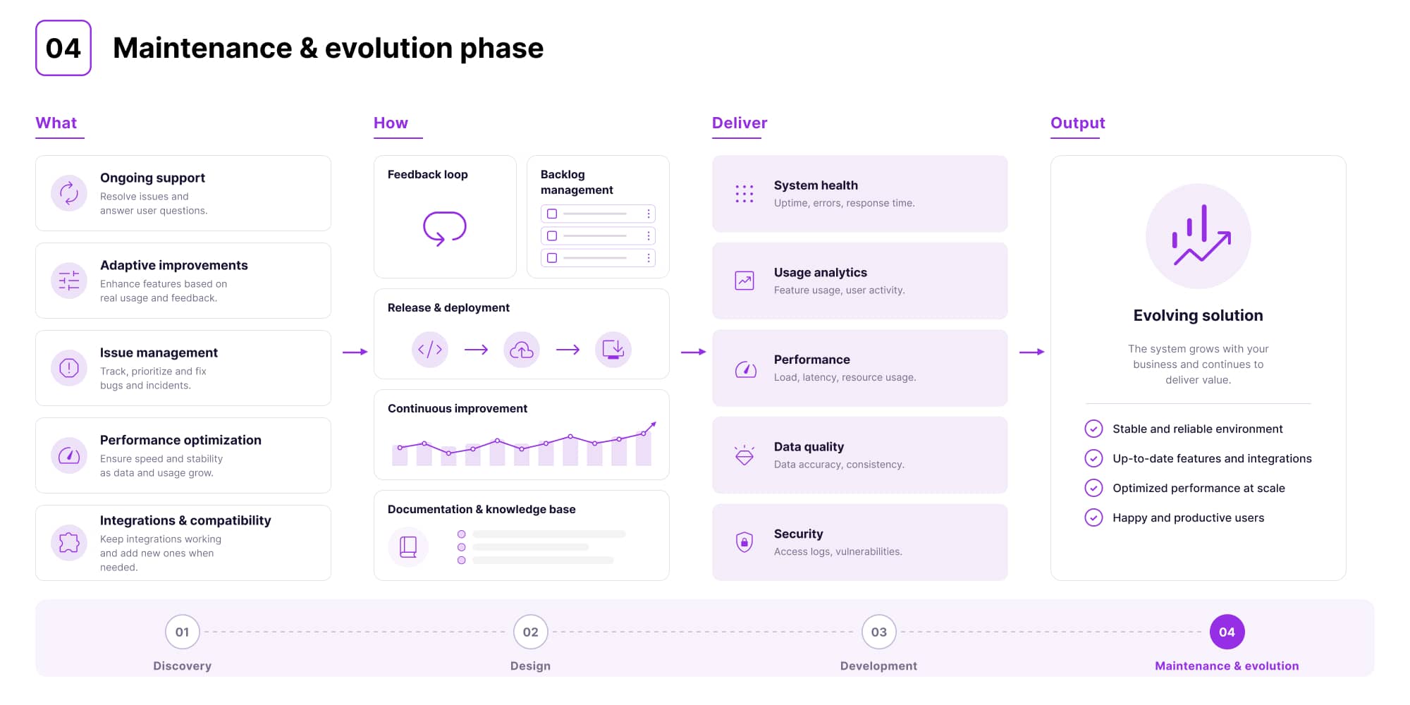
Once the system is live, the work doesn't stop. This phase focuses on monitoring performance, supporting users, fixing issues, and continuously improving the product based on real feedback.
Helping teams establish new standards and workflows they can propagate through the system. Rather than leaving process definition to individuals, the software becomes a vehicle for standardization.
What matters most here is that requirements rarely stay the same. As users start working with the system, new needs appear, edge cases become visible, and priorities shift. A good partner anticipates this early, already at the design stage, and builds the system in a way that allows it to evolve without breaking existing logic.
At Synergy Codes, this is supported by a dedicated expert team focused on complex diagram algorithms. They are involved not only during development, but already at the estimation and design stages, ensuring that the system can handle future complexity from day one.
What is typically monitored and improved over time?
- System performance – ensuring fast and smooth work,
- User experience – simplifying actions, improving clarity, reducing unnecessary steps,
- Data consistency – keeping diagrams aligned with system logic and data sources,
- Validation logic – refining rules so they better support real engineering workflows,
- Scalability – making sure the system works equally well as usage grows,
- Integrations – maintaining reliable communication with other systems or new data sources,
- New needs – introducing features based on real usage and evolving workflows.
Outdated electrical drawings cost teams 30% of project time.
Score your teamSummary – benefits of custom approach vs. off-the-shelf solutions
Custom electrical schematic configurator for your team
At some point, the challenge is no longer about better diagrams, but about whether your tools reflect how your systems actually work.
This is where custom software development for electrical industry becomes a practical step. It allows teams to move from static diagrams to systems that support real workflows, validation, and faster decision-making. The same applies to visualization of electrical flow – when done right, it becomes a functional layer of the product, not just a visual one.
If your current tools are starting to limit how you work, it may be the right time to consider a different approach. Synergy Codes supports teams in building solutions tailored to their real needs.
→ If you want to explore what that could look like in your case, contact us.
- What problem does a custom electrical schematic configurator actually solve?
It removes bottlenecks caused by slow, request-based workflows. In many teams, even a small change in a diagram has to pass through several steps – an engineer reports it, a developer implements it, QA verifies it and only then it goes live. This turns simple updates into long delays. A custom tool lets you make changes instantly, reduce errors and keep everything consistent.
- Will engineers still need developers to make changes?
No – that's one of the key benefits. A custom configurator gives engineers direct control over diagrams and configurations, so they can work faster without waiting for implementation or release cycles.
- Is a custom configurator a viable CAD alternative?
Yes – especially for complex systems. While traditional CAD tools focus on drawing, a custom solution goes further by integrating validation, business logic and real-time data, making diagrams part of a working system, not just static visuals.
- How long does it take to build a custom electrical schematic configurator?
It depends on the complexity of the system, required integrations, and the scope of the electrical layout or diagram logic. Most projects follow four phases – discovery, design, development, and maintenance. Synergy Codes accelerates delivery by building on proven frameworks like React Flow, GoJS, and ngDiagram.
- What industries benefit most from custom electrical design software?
The biggest value comes in industries where diagrams support real operations – especially energy, industrial engineering, simulation, and AV broadcast. This is particularly true when teams need advanced control logic visualization or more specialized workflows than standard tools can offer.
- Can a custom solution integrate with existing tools and data sources?
Yes – custom solutions are built to work within existing environments. They can support API integrations, data import/export, and real-time synchronization with other tools, which makes them a strong option for teams looking beyond generic tools or basic SCADA alternatives.
Jakub is a Software Developer specializing in data visualization, diagram layouts, and AI-driven workflow optimization. Known for challenging conventional thinking, he explores complex problems from fresh perspectives and turns deep technical insight into practical business impact. From transforming early-stage concepts into scalable systems to accelerating engineering workflows from weeks to days, Jakub combines curiosity, innovation, and hands-on expertise to deliver smarter solutions.

Find how we can help you enhance your software and win more deals
Contact us to discuss your project. After you submit the form, we’ll get in touch with you within 48 hours to arrange a call.


.png)