Single line diagram software: what electrical teams should compare before they commit

This guide breaks down the capabilities worth comparing, the assumptions that can lead to a poor fit, and the questions electrical teams should ask before commi

Choosing single line diagram software isn't just about finding a tool that draws electrical schematics. The real differences emerge when teams need to manage engineering data, automate diagram generation, enforce validation rules, or integrate with existing systems.
Single line diagram software helps electrical teams create and maintain simplified models of power systems, showing how major components connect without drawing every conductor individually. The category covers everything from drafting tools to engineering platforms that connect diagrams with calculations, validation, operational data, or company-specific design rules.
That range makes comparisons harder than they first appear. Tools may both create a clean electrical single line diagram while supporting very different engineering processes behind it.
Choosing the right software starts with deciding what the diagram needs to do after someone draws it.
What is single line diagram software?
A single line diagram, also called a one-line diagram or SLD, represents an electrical system using simplified connections between major components such as buses, transformers, breakers, generators, and loads.
Single line diagram software provides an environment for creating and maintaining those models digitally. At the simpler end, the software may focus mainly on drawing and documentation. Engineering-focused platforms can connect the diagram to equipment data, topology, calculations, or operational information.
Tools such as ETAP treat the single line diagram as an interface into the underlying electrical network model rather than an isolated drawing. General CAD products occupy a different position, providing electrical symbols and drafting capabilities without necessarily modeling every company-specific engineering process around the diagram.
Neither model is automatically right for every electrical team. Problems usually start when teams compare tools only on the appearance of the canvas rather than the work that needs to happen around it.
Start with the electrical model, not the drawing interface
A polished editor can still be the wrong choice if the underlying model can't represent the system your engineers work with.
Before looking at convenience features, check what an object on the diagram actually represents. Does a breaker carry engineering data? Can the software understand electrical connectivity rather than simply drawing a line between two symbols? Can the same component be referenced elsewhere without creating another disconnected copy?
Those questions become more important as diagrams grow and start feeding other engineering work.
Synergy Codes has encountered the same issue in custom electrical projects. General diagramming primitives can make a diagram look correct while leaving the engineering meaning outside the model.
Our electrical design software work instead starts from a working SLD foundation that can be extended with the client's own component model and validation rules.
Compare how the software handles engineering data
An SLD often starts as a drawing problem and turns into a data problem later.
Engineers need component attributes to remain consistent with the diagram. Another system may own equipment information. A study tool may generate results that need to appear on the same model. Changes to a feeder or device can affect documentation somewhere else.
Software that treats the diagram as a collection of shapes leaves more of that synchronization to the team. A data-aware platform can associate diagram objects with structured information and use the same model across several operations.
The practical comparison isn't simply “does it support component properties?”. Look at where those properties come from, how they're updated, and whether the same information must be re-entered elsewhere.
This becomes particularly important in organizations already using ERP, SCADA, internal equipment databases, or established CAD systems. Replacing every system is rarely necessary. Moving data between them without repeated manual work is often the bigger opportunity.
Our article on when standard electrical CAD tools aren't enough looks specifically at this gap between drawing software and the workflow surrounding it.
Check what “automatic” actually means
Automation appears on almost every modern electrical software feature list, but the word can mean very different things.
At one end, software may automate spacing or alignment after engineers create a diagram manually. More advanced systems can generate complete SLD structures from engineering data, then regenerate the drawing as specifications change.
Synergy Codes' current electrical foundation uses deterministic layout algorithms for diagrams containing thousands of components. Routing logic maintains clean electrical connections while the diagram changes, and the same foundation can be extended with project-specific generation rules.
Automatic generation becomes most valuable when teams repeatedly create similar diagrams from known data. Instead of redrawing each variation, the software can treat the diagram as an output of the engineering model.
4 myths worth dropping before you choose SLD software
Feature comparisons get easier once a few common assumptions disappear.
Myth 1: “If it can draw an SLD, it can support our SLD workflow”
Creating the picture is only one part of the job.
The difficult work may happen before or after the drawing: importing equipment data, applying company standards, running checks, updating dependent documents, or sending the result into another system.
A tool can produce a correct-looking one-line diagram and still leave most of that workflow manual. Before evaluating drawing features, map what engineers currently do from the moment new project data arrives until the final documentation is approved.
Myth 2: “More electrical features automatically mean a better fit”
A large engineering suite can be extremely capable and still introduce functionality your team doesn't need.
An organization building network studies has very different requirements from a manufacturer generating standardized diagrams from product configurations. One may need advanced simulation. The other may care much more about deterministic generation and tight integration with an internal product database. Feature count doesn't tell you how much of the team's actual process the software covers.
Myth 3: “Custom software means replacing our CAD stack”
Custom electrical software doesn't have to become a replacement for AutoCAD Electrical, EPLAN, ETAP, or another established engineering tool.
A purpose-built application can sit earlier in the process, automate one repetitive stage, enforce internal rules, or connect systems that currently require manual handoffs. Final drafting or specialist analysis can remain in the existing toolchain. In many projects, integration is more useful than a wholesale migration.
Myth 4: “Diagram performance is just a frontend problem”
Large electrical diagrams put pressure on much more than rendering.
Routing calculations become heavier. Changes may trigger validation or layout work across a substantial part of the model. Real-time data adds another stream of updates. Keeping several thousand interactive components usable requires decisions in the data model and algorithms as well as the rendering library.
Our electrical work currently includes auto-layout that holds up under thousands of components, while other custom diagram systems we've built operate at even larger scales.
Look closely at validation
Electrical software can do more than warn engineers after a diagram is complete.
A system with access to the right rules can flag invalid connections as the design is being created. It can restrict unsupported component combinations or check the diagram against company-specific constraints.
Generic software usually has to support generic rules. Internal engineering processes tend to contain exceptions and standards that are much more specific.
A company may have its own equipment combinations, naming conventions, conduit rules, or required properties. Encoding those rules into the tool moves knowledge out of spreadsheets and review checklists and into the design workflow itself.
We published a separate guide on why electrical standards compliance often breaks down in tools rather than engineering teams, and it covers this validation problem in more depth.
Evaluate symbol libraries in the context of your standards
Most electrical diagram tools provide some form of symbol library. The important question is how well that library fits the work your engineers produce.
Teams working across IEC, IEEE, ANSI, or company-specific notation may need several representations of similar equipment. A manufacturer's internal tools may also include proprietary components that don't exist in any standard library.
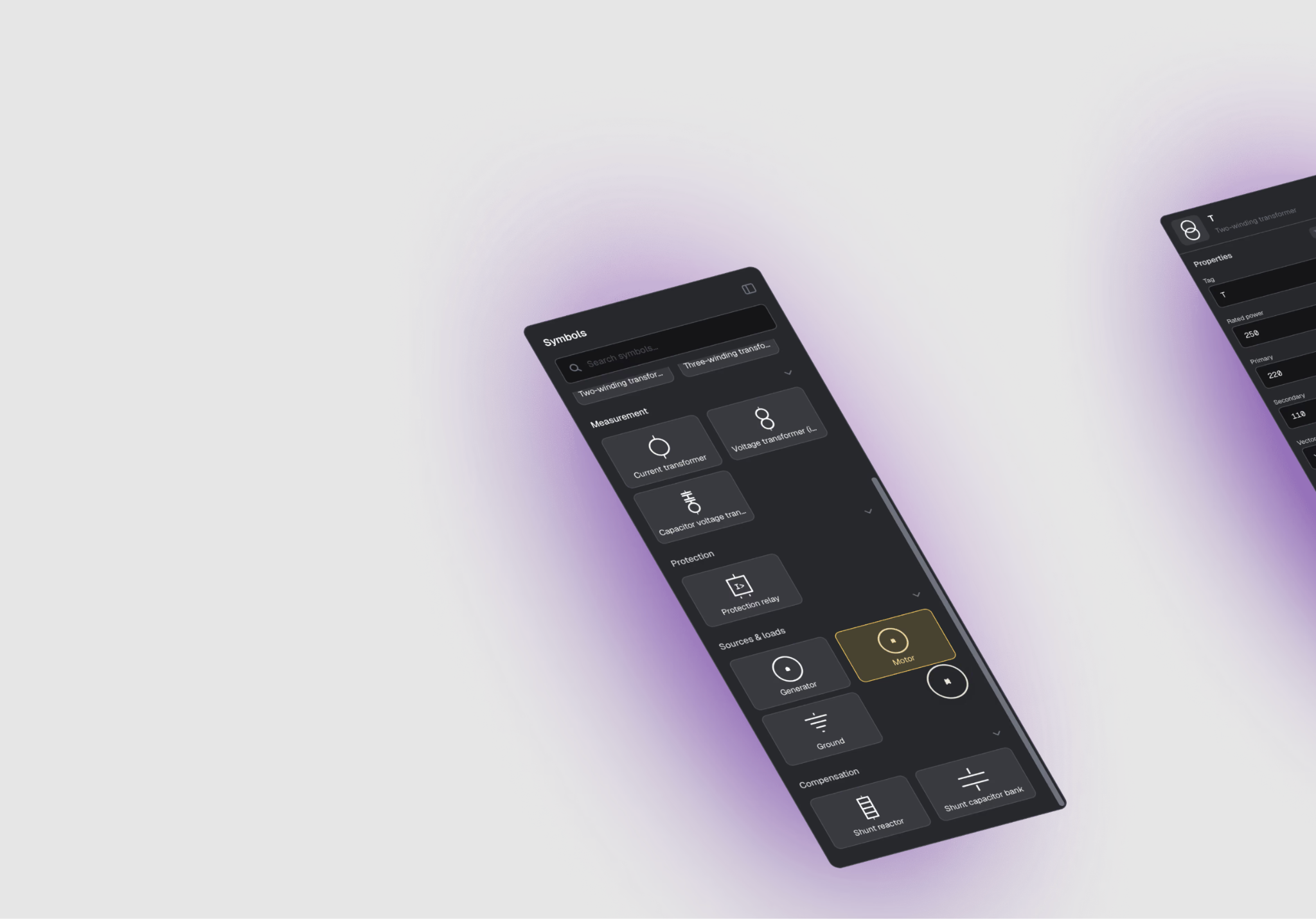
Check how easy it is to add a symbol and connect it to the right underlying component type. Updates should be manageable centrally rather than requiring every engineer to maintain their own collection of drawing assets.
Symbol consistency becomes particularly valuable when diagrams are generated automatically. Generation rules are only reliable when the component definitions feeding them are controlled.
Test routing on a real electrical diagram
Connection routing rarely looks difficult in a product demo with a dozen components. Dense SLDs expose the limitations quickly.
As the model grows, wires need to avoid other objects and remain readable after elements move. Orthogonal routes should stay clean without forcing engineers to spend time adjusting every segment manually. For generated diagrams, routing becomes even more important because users aren't manually placing every object to make the layout work.
Our electrical design foundation combines auto-layout with custom connection-routing logic, while our broader diagramming work includes dedicated algorithms for dense technical graphs. Teams comparing software should test these capabilities on representative project data rather than the vendor's smallest sample.
Think about what happens after an engineer changes something
A diagram is rarely finished forever. Equipment changes. A project revision arrives. Another engineering system updates its data. Someone corrects a specification that affects several parts of the drawing.
Good SLD software should reduce the amount of reconciliation required after those changes.
For some teams, version history and controlled collaboration may be enough. Others need dynamic regeneration of the diagram from updated engineering data. More connected systems can propagate changes into documentation or show live operational information directly on the same schematic.
Our article on managing changes in electrical control system documentation explains why the update process is often more expensive than producing the first drawing.
For a practical example of how these requirements translate into an actual application, see our single line diagram editor case study. It shows how a custom SLD environment can be designed around a specific engineering workflow rather than forcing the workflow to fit a generic drawing tool.
Check how well the software handles large diagrams
SLD complexity isn't measured only by the number of visible symbols. Connections, nested structures, metadata, validation, and interactive states all influence performance.
Ask vendors or development teams to test realistic files. If the largest production diagram has 2,500 components, benchmarking a 100-node demo doesn't tell you very much.
Useful tests include opening time, pan and zoom responsiveness, the delay after moving a component, layout regeneration, and how quickly validation reacts to a change.
Large models also raise UX questions. Engineers need ways to navigate between sections and inspect detail without losing the wider network context.
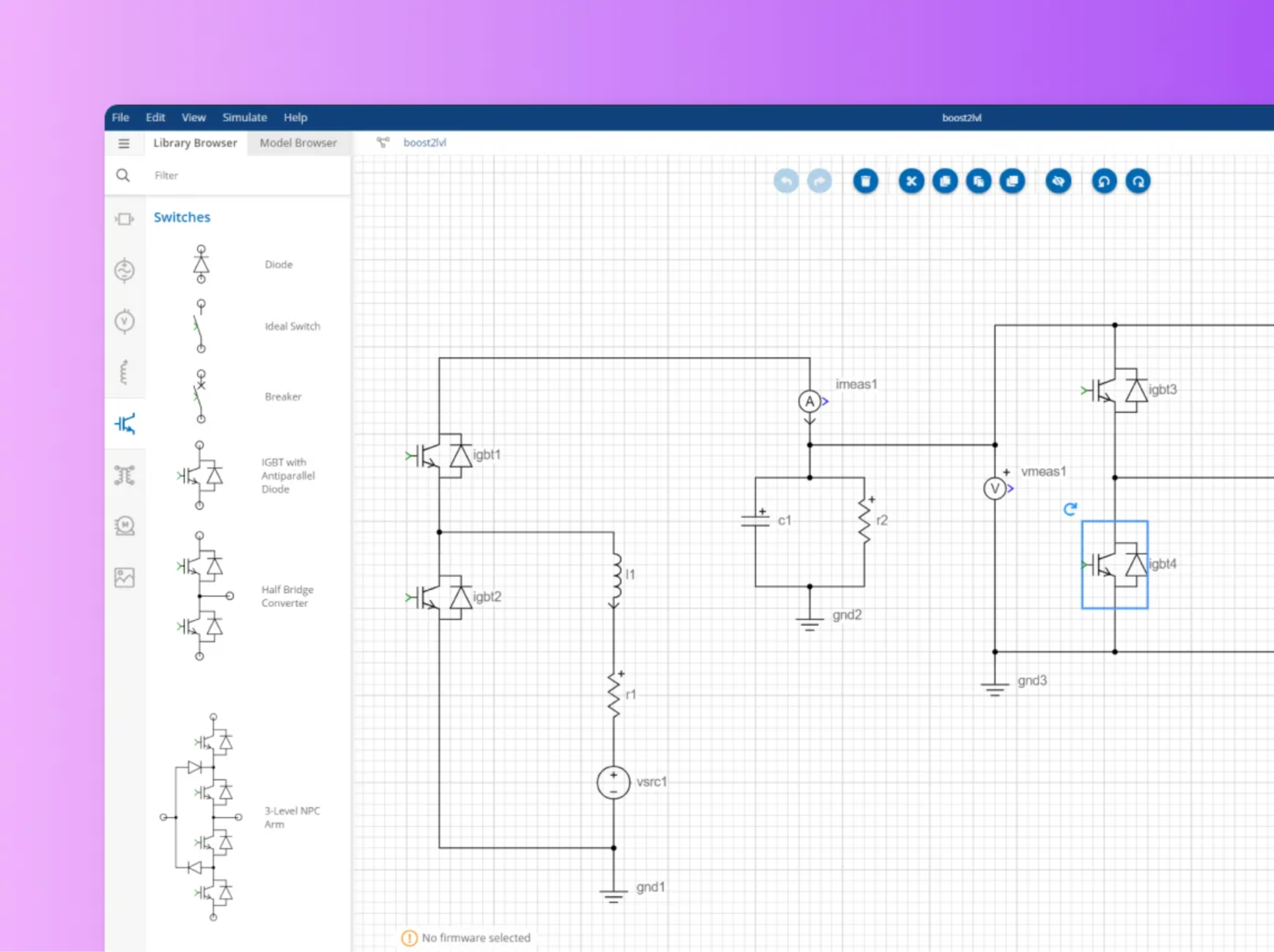
The associated schematic editor case study covers a custom environment developed for OPAL-RT, including reusable models and electrical circuit visualization.
Decide how much integration the SLD software needs
Few engineering organizations operate from one system.
Electrical teams may already depend on CAD tools, product databases, ERP, SCADA, simulation software, and internal platforms. New SLD software needs a clear place in that environment. File import and export may be enough when systems interact occasionally. Tighter workflows can require API integration or a shared data model.
Electrical platforms like this have to meet the systems already in place: CAD tools such as AutoCAD or EPLAN, simulation environments such as Simulink, operational systems such as SCADA or ERP, and internal APIs. Synergy Codes can build that connecting layer as part of the platform rather than leaving it as the client's own integration project.
Before committing to a tool, map the systems that feed the diagram and the systems that consume its outputs. Integration requirements tend to become obvious once that map exists.
Collaboration is more than sharing a file
Several engineers may need to review the same system over the life of a project. File-based collaboration can work well when changes are infrequent, but it becomes harder when diagrams evolve continuously.
Web-based tools can support a different workflow. Engineers can work from a shared model, while version history records what changed. Review processes can also happen around individual components rather than through entire exported drawing packages.
Not every team needs real-time collaboration, so it shouldn't become a checkbox requirement without a use case. The value appears when file exchanges and version reconciliation already consume meaningful engineering time.
Compare outputs before comparing editors
Teams often focus on how the drawing is created and leave export until the end of the evaluation. The output may actually be the more important requirement.
One team needs publication-ready PDF drawings. Another has to continue editing in AutoCAD. A manufacturer may generate a BOM from the same configuration, while an industrial system could use the diagram as an operational view connected to live equipment. List the required outputs before selecting the authoring tool. A comfortable editor doesn't help if the final diagram has to be rebuilt somewhere else every time.
Single line diagram software comparison checklist
A practical evaluation doesn't need hundreds of feature rows. Start with the areas that affect the engineering process.
See it in practice: our open-source SLD template
Five rows in the checklist above are easier to judge on a working editor than on a feature list: electrical model, component library, routing, outputs, and customization. Synergy Codes publishes an open-source single line diagram template, built on our ngDiagram library, that you can open straight in the browser.
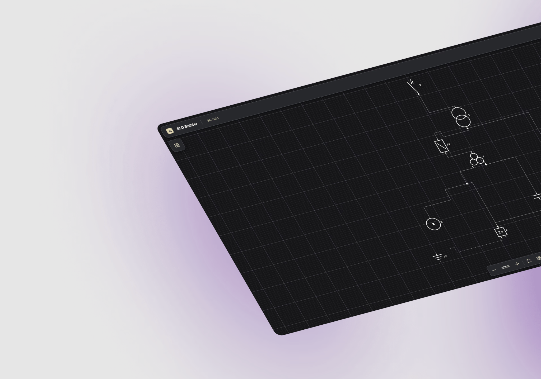
The demo opens on a 220/110 kV transformer bay. Each symbol carries its own engineering properties, which you edit in a panel generated from the symbol's definition. The IEC 60617 library is managed through one central pipeline, so adding a new component doesn't mean sending new drawing assets to every engineer. Wires connect terminal to terminal with orthogonal routing, stay attached as symbols move, and create real junctions in the model where they meet.
A finished diagram exports to SVG or DXF, so work can continue in the CAD tools the team already uses.
The application code is MIT-licensed and organized into modules that can be extended independently. That makes it a practical starting point for a company-specific editor, whether your team extends it in-house or with us.
Open the live demo or view the template on GitHub.
Every piece of software imposes some structure. The decision becomes much easier once a team knows which parts of its process are genuinely unique and which can comfortably follow an existing tool.
When off-the-shelf SLD software is enough
Custom software shouldn't be the default answer.
Established electrical engineering platforms make sense when their built-in model matches the work, the required calculations already exist, and integrations don't need heavy customization. A team primarily carrying out standard studies may gain far more from a mature engineering suite than from recreating those capabilities.
The case for something more tailored appears when work starts happening around the software instead of inside it. Engineers may copy the same information between several systems. Internal rules remain in spreadsheets or people's heads. Drawings need extensive cleanup after generation. A product team may also be trying to expose electrical design capabilities to customers through an interface traditional engineering software was never designed to provide.
At that point, comparing another off-the-shelf package may not address the underlying problem.
If several of those describe your team, our electrical schematics checklist helps assess the gap across five areas, from diagram accuracy and change management to scalability.
When your own process is more important than the feature list
Electrical teams rarely wake up wanting custom diagram software. They reach that point after their process becomes too specific for a generic tool or too fragmented across several of them.
The question then changes from “Which SLD application has the most features?” to something more useful: “Which parts of our process should the software understand?”
That may mean encoding internal standards into validation, generating diagrams from existing engineering data, or connecting an editor to systems already used across the organization.
Synergy Codes starts from an existing single line diagram and electrical design software foundation rather than an empty canvas. Teams can keep the parts of their current toolchain that already work and extend the layer where their own process starts to become different.
Content Marketing Specialist who's spent the last decade making tech topics actually readable. With an MA in Brand Communication, Ida has crafted content strategies for several IT companies. Her portfolio spans from Kubernetes tutorials to enterprise software guides, now focusing on data visualization and diagramming solutions.

Find how we can help you enhance your software and win more deals
Contact us to discuss your project. After you submit the form, we’ll get in touch with you within 48 hours to arrange a call.