Web-based schematic editor: the hard parts

A canvas with symbols is the easy part. Pin identity, first-class nets, junction rules and grid routing decide whether a schematic editor survives production.
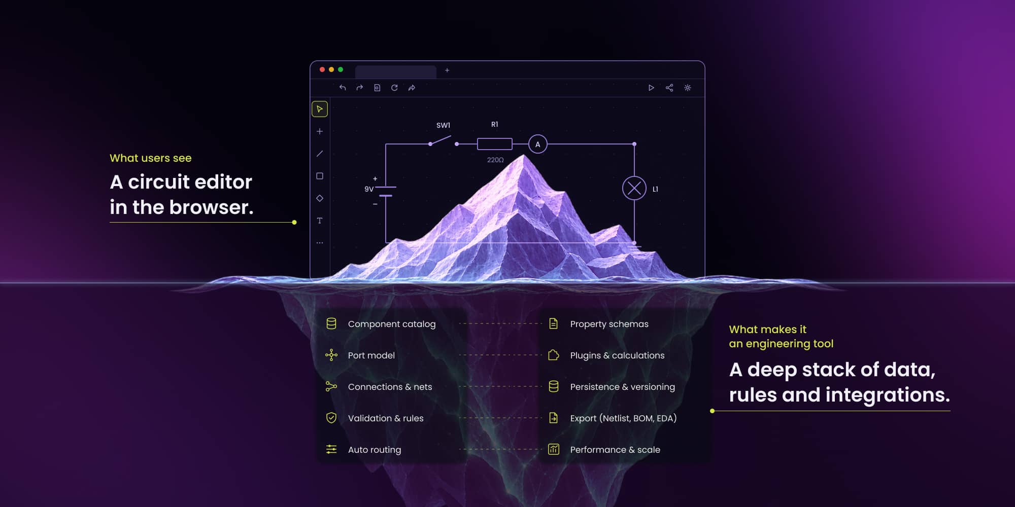
A web-based schematic editor is hard because it must preserve electrical meaning, not just drawings. Stable pin identity, first-class nets, junction topology, grid-disciplined routing and a catalog with orderable part identity separate a production tool from a canvas demo. The ngDiagram electric-circuit starter covers the interaction layer; the domain features remain custom engineering work.
A circuit editor can look convincing long before it behaves like one. A first prototype needs a canvas, electronic symbols and a way to connect them. Production work begins when connections need stable pin identity, nets have to survive edits, wires need predictable geometry and the data model has to support real engineering and product workflows.
Synergy Codes starts such projects from custom circuit design software and the public ngDiagram electric-circuit starter rather than from a blank drawing canvas. The starter covers concept-stage schematic interaction, not PCB layout or electrical validation.
ngDiagram is Synergy Codes' Apache 2.0-licensed Angular diagramming engine for interactive node-and-edge applications. ngDiagram's generic ports are the primitive used to model component pins. In EDA vocabulary a port is something else – a hierarchical sheet connector – so this article says "pin" whenever it means a component terminal.
Why generic node editors stop short
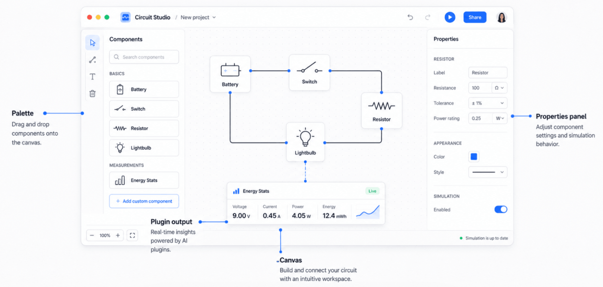
React Flow and GoJS can draw boxes and lines, but they do not understand component pins, electrical nets, implicit connectivity or schematic junction rules. That missing domain layer is where a circuit editor starts to diverge from a flowchart editor.
A note on vocabulary: in circuit theory a "node" is a net. In graph terms a component is the vertex. This article uses "component" for the graph vertex to avoid mixing the two meanings, and the ambiguity itself is a useful reminder that a generic node-editor model does not carry enough electrical meaning on its own.
The canvas has to preserve two different things at once: visual geometry and electrical topology. Moving a symbol should change where a wire bends without silently changing which pins belong to the same net.
For a React-only product team, the framework choice is a real architectural decision. ngDiagram is Angular, so it is not a drop-in React component. A team either creates a bounded integration around the Angular editor or keeps a React-native canvas and reimplements the circuit-specific semantics there. The hard work discussed below exists in either case.
Pin identity is only the first layer
A generic diagram edge connects one graphic object to another. A schematic connection relates specific component pins, and those pin identities need to remain stable through movement, redraws and serialization.
Use a power MOSFET as an illustrative example, not as a claim about the current public demo catalog. A power MOSFET has three logical pins – gate, drain and source – and its symbol may expose a fourth body terminal. On the board it may present five or more pads because the tab is tied to the drain and the source can occupy several pads. One logical pin can map to multiple physical pads, which is why schematic pin identity and footprint pad identity have to be separate concepts from day one.
The public ngDiagram electric-circuit starter currently stores pin numbers and stable pin-to-pin connections. It does not store electrical pin types or perform ERC, so "pin-aware" here means identity and topology, not an understanding of electrical function.
Building a circuit editor? See what custom circuit design software covers
Check our offer.png)
A production model should be net-centric
A connection object that only stores "source component / source pin / target component / target pin" is enough for a small visual demo, but it is not a complete schematic model. A production editor needs the net itself to become a first-class object so it can have a name and collect every connected pin.
{
  "nets": [
    {
      "name": "LED_A",
      "connections": [
        { "ref": "R1", "pin": "2" },
        { "ref": "D1", "pin": "1" }
      ]
    },
    {
      "name": "GND",
      "connections": [
        { "ref": "D1", "pin": "2" },
        { "ref": "BT1", "pin": "2" }
      ]
    }
  ]
}
Note what this model buys. A net is a first-class object with a name, so a power symbol or a net label can connect pins with no continuous wire drawn between them. One GND symbol tying forty pins is normal, and a purely edge-based diagram model cannot express that semantics cleanly.
This is an extension beyond the public starter. The current JSON export contains components and pin-to-pin topology; named net objects, net labels and implicit connectivity belong to the production domain model a custom implementation would add.
The hard parts a real schematic editor still has to budget
Junctions and orthogonal routing are useful, but they are not the end of the problem. A production editor should explicitly budget several capabilities that the public starter does not provide today:
- Implicit connectivity: net labels and power symbols that connect pins without drawing one continuous wire.
- Hierarchical and multi-sheet design: production schematics can span many sheets and need explicit sheet connectivity.
- Buses: groups such as D[0..7] need to behave as structured electrical objects, not eight unrelated labels.
- ERC with electrical pin types: output-to-output conflicts, unpowered power pins and unconnected required inputs need domain rules.
- Annotation, topology-aware undo and ECO: reference designators, reversible graph mutations and comparison against the last layout transfer need deterministic behavior.
Naming these as unsolved is more useful than pretending a concept-stage canvas is already a full EDA system. What is schematic capture? covers the logical outputs and the boundary with PCB layout in more detail.
Orthogonal routing is a connectivity convention, not decoration
Schematic wires are orthogonal by convention, and the reason is the grid: pins sit on a fixed pitch and wires snap to it because off-grid endpoints can produce wires that look connected and are not. Grid discipline is a connectivity requirement, not a cosmetic one, which is why snapping belongs in the canvas rather than being bolted on later.
The ngDiagram electric-circuit starter includes orthogonal routing, grid-aligned geometry and manual reshaping. Endpoints stay tied to their component pins as the graphic objects move.
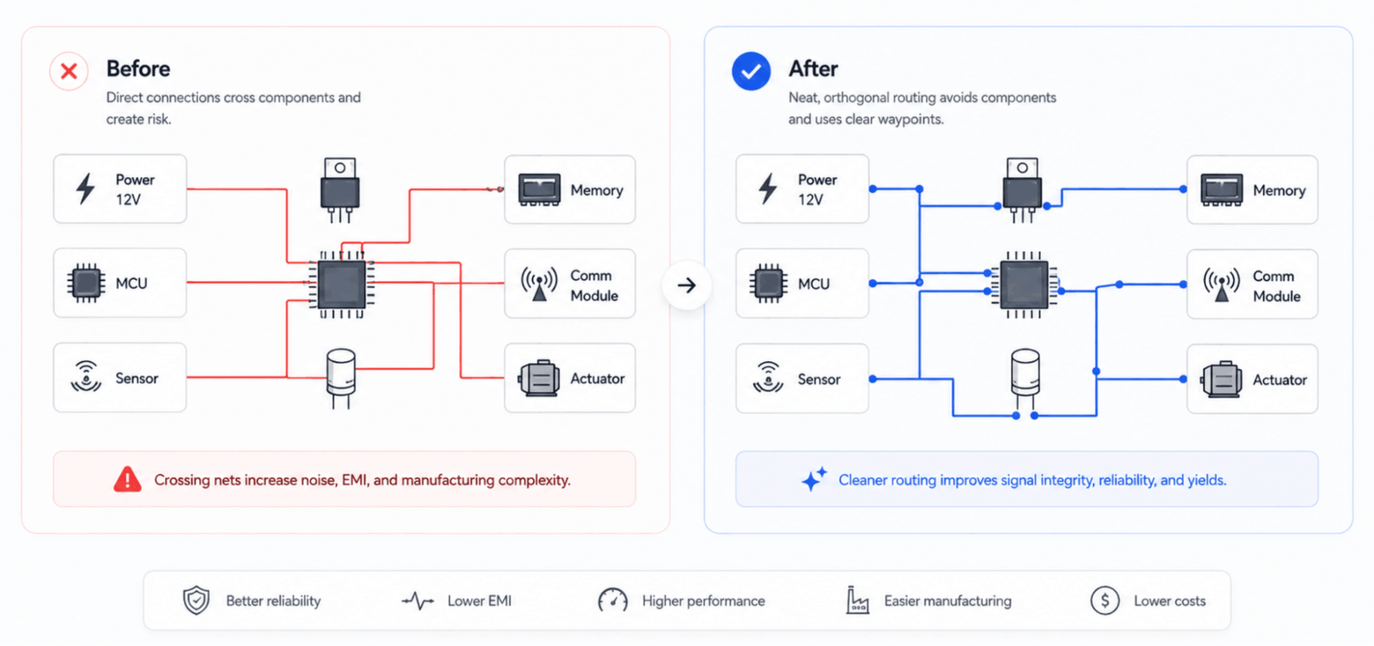
Automatic routing solves only part of the editing problem. Engineers also want to drag a vertical segment, create clearance around a symbol or align several wires. Segment editing has to preserve orthogonality, remove zero-length geometry and update connected junctions without changing the electrical relationship.
Wire-to-wire junctions need topology and drafting rules
Branching from the middle of an existing wire changes both the drawing and the graph. The editor has to create a branch point, preserve the original connection, attach the new branch, serialize the topology and later remove the junction cleanly if that branch disappears.
Junction branching with merge-back is table stakes in desktop EDA and absent from generic node editors, which is why a flowchart canvas cannot simply be renamed a schematic editor. It is also constrained by a drafting rule worth knowing: four-way junctions are avoided, and a crossing is offset into two three-way tees because an ambiguous solder dot on a four-way crossing can be misread.
The public starter supports branching from an existing wire, junction cleanup and merge-back after deletion. That is real circuit-specific interaction, but it should be described as solved table stakes rather than "one of the hardest parts" of EDA.
A component catalog is an application architecture problem
A small demo can hard-code a dozen symbols. A commercial product cannot. The current public starter is data-driven for pins, reference prefixes, values and property fields; symbol artwork is still one inline case per component type. Decoupling artwork into loadable assets is the first extension Synergy Codes makes for a vendor catalog of any real size.
The public demo catalog contains 17 items: resistor, capacitor, inductor, potentiometer, fuse, crystal, diode, LED, Zener diode, NPN transistor, PNP transistor, NE555, switch, push button, battery, +5V and GND. It does not contain a MOSFET, op-amp, microcontroller or connector, so examples using those parts in this article are illustrative implementation cases rather than claims about the demo.
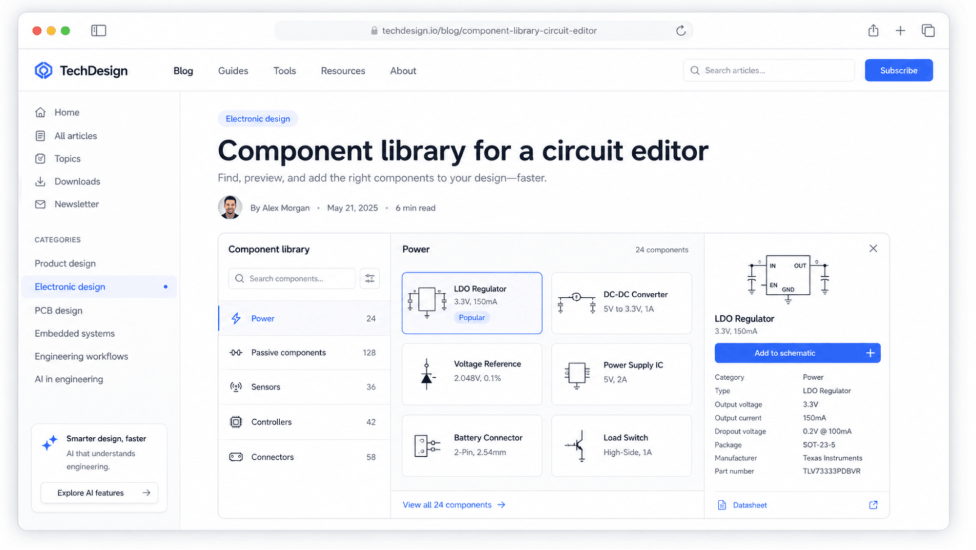
For a vendor implementation, a catalog record becomes the object of record behind the symbol. It can carry orderable part identity, properties, approved alternates and commercial metadata, while the canvas renders and edits the visual representation.
A procurement-ready BOM starts with part identity
The public ngDiagram electric-circuit starter does not export a BOM or CSV. A custom application can add that workflow, but the output should look like procurement data rather than a three-column demo table.
| Ref Des | R1, R2 | D1 |
|---|---|---|
| Qty | 2 | 1 |
| Value / Description | 10 kohm, 1%, 0.1 W | Red LED |
| Package | 0603 | 0603 |
| Manufacturer | Illustrative | Illustrative |
| MPN | MPN_TO_DEFINE | MPN_TO_DEFINE |
| Internal PN | RES-10K-0603 | LED-RED-0603 |
| Alternates | Approved alternate set | Approved alternate set |
| DNP | No | No |
A BOM is only as good as the part identity behind it, which is why the catalog entry, not the symbol, is the object of record.
See how Synergy Codes built a schematic editor for OPAL-RT
Read case studyExport needs an honest boundary
The documented public export formats of the ngDiagram electric-circuit starter are SVG, JPEG, DXF and JSON. DXF is useful for CAD-oriented drawing exchange but does not carry schematic connectivity. JSON is the structured handoff because it carries component and pin-to-pin topology.
There is no built-in one-click export from the public starter into Altium, KiCad or OrCAD X. A custom project maps the JSON model into the target format or internal pipeline required by that customer. The same applies to BOM generation: it is application work layered on top of the structured part model, not a starter feature.
Performance has two different costs
Spatial hashing, reactive state and batched operations address the geometry side of a large canvas: hit-testing, redraw work and culling. The schematic-specific cost is connectivity – recomputing which pins belong to which nets after an edit, ideally incrementally rather than from scratch.
Production schematics can run to thousands of components across dozens of sheets, which is exactly why they live in tools such as Altium and OrCAD X. A concept-stage canvas targets hundreds of components on one sheet, and that bound is a design decision rather than an accidental benchmark claim. The public ngDiagram goal is "hundreds of components"; without a published benchmark, the article should not claim more.
A production example: hierarchical power-electronics editing
Synergy Codes has delivered a schematic editor for a real-time simulation vendor in power electronics. The application used a cataloged block library, hierarchical subsystems, parameter configuration and hardware I/O mapping, and it was released as both a web application and a desktop build. That project is closer to the real hard parts than a small component demo because hierarchy, parameters and hardware mapping are domain behavior rather than drawing behavior.
Read the OPAL-RT Schematic Editor case study and open the live ngDiagram circuit demo.
Why start from ngDiagram
ngDiagram provides the reusable canvas primitives, while the ngDiagram electric-circuit starter adds stable pin connections, junction branching, merge-back, orthogonal routing, grid snapping, a small component catalog and structured JSON export. It does not include undo/redo or keyboard navigation, and those items should be treated as application work rather than starter capabilities.
The Apache 2.0 license matters commercially. A team can inspect and extend the canvas without a per-seat runtime model, and Synergy Codes states that the client owns the custom product code built for its implementation. Self-hosting is available when a project's deployment requirements call for it.
The public repository lets a technical team inspect the starter before committing to custom development.
The hard part is preserving domain meaning through edits
A web-based schematic editor becomes credible when the design model survives hundreds of edits without losing electrical meaning. Pins need stable identity, nets need first-class representation, junctions need deterministic topology, routes need grid discipline and catalog entries need orderable part identity.
The public starter solves part of that interaction layer. A production application still has to add the domain features its use case requires, especially named nets, implicit connectivity, hierarchy, ERC, annotation and downstream change management. That is the correct place for custom engineering effort.
For the surrounding market context, read AI in PCB and circuit design: what's real, what's hype. For the logical definition and EDA boundary, read What is schematic capture?.
- Why is a schematic editor harder than a flowchart editor?
A schematic editor has to preserve electrical topology as well as visual geometry. It needs stable pin identity, nets, junction semantics, grid-aligned wire behavior and domain rules that generic diagram libraries do not provide automatically.
- Should a schematic data model store nets as first-class objects?
For production use, yes. First-class net objects make names, power symbols, labels and implicit connectivity explicit in the model. A simple edge-only representation becomes awkward once the design grows beyond direct pin-to-pin wires.
- Can React Flow or GoJS be used for a circuit editor?
They can provide a general diagram canvas, but the circuit semantics still have to be built: pins, nets, junctions, routing rules and electrical-domain behavior. A team should evaluate the cost of that domain layer separately from the cost of drawing nodes and edges.
- What does the public ngDiagram electric-circuit starter export?
The documented public exports are SVG, JPEG, DXF and JSON. JSON carries component and pin-to-pin topology; direct EDA mapping and BOM export are custom application work rather than built-in starter features.
- Where can you try ngDiagram before building a schematic editor?
ngDiagram is available at ngdiagram.dev, with documentation and live examples that include the electric-circuit starter. It is Synergy Codes' Apache 2.0-licensed Angular diagramming engine, so a team can evaluate the canvas before committing to custom development.
As the founder and CEO of Synergy Codes, Maciej guides Fortune 500 companies and startups in identifying how custom diagramming solutions can transform their operations. With 15+ years in the field, he leads a team of experts who've delivered 170+ implementations across diverse industries, streamlining workflows and enhancing decision-making.

Find how we can help you enhance your software and win more deals
Contact us to discuss your project. After you submit the form, we’ll get in touch with you within 48 hours to arrange a call.

.jpg)