What is schematic capture (and why it's moving to the browser)

Schematic capture turns symbols and wires into a machine-readable circuit model. See what it contains and why concept-stage design is moving to the browser.
.jpg)
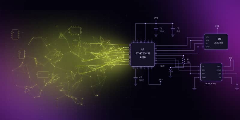
Schematic capture creates the logical, machine-readable model of a circuit: symbols, pins, wires and nets that produce a netlist for ERC, simulation and PCB layout. Browser-based editors now cover the concept stage of that flow, which lets a company embed guided schematic design into its own product and quoting experience.
Before a circuit becomes a physical board, its components and electrical connections need a logical model. Schematic capture is the process used to create that model: engineers place symbols, connect component pins into nets, annotate the design and produce the data later stages of electronics development depend on.
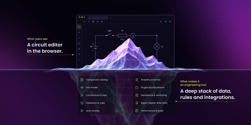
The important output is not the picture alone. The schematic carries machine-readable connectivity that can feed ERC, simulation and transfer into PCB layout. A browser-based editor can cover part of that early flow when a company needs a guided or customer-facing design experience rather than a complete desktop EDA suite.
Synergy Codes builds custom circuit design software for that narrower layer: concepting, component selection and schematic topology around a company's own product data and workflow.
What is schematic capture?
Schematic capture is the process of creating a logical, machine-readable representation of an electronic circuit using component symbols, pins, wires, nets and design constraints.
A schematic editor stores more than shapes. It records which component pin belongs to which electrical net and preserves that relationship while the drawing changes.
The output of schematic capture is a netlist – a machine-readable list of every net and the component pins it connects. Downstream tools read connectivity data, not the visual drawing alone: simulation, PCB layout and electrical rule checks all depend on the circuit model.
A basic LED example makes the difference concrete. Use a 5 V source, a current-limiting resistor – 330 ohms for a 2 V red LED at roughly 9 mA – the LED itself and the ground return that closes the loop. The resistor value follows from (5 V - 2 V) / 9 mA. A diagram lets a person read that circuit; the model lets software reason about the same four terminals and two nets.
Planning a browser-based circuit design tool? See what it takes
Check our offer.png)
What a captured schematic contains
Component symbols
Symbols represent parts without reproducing their physical appearance. A resistor may use a rectangle or zigzag symbol, while an IC may be shown as a larger block with many named pins. The component record behind the symbol can carry manufacturer, MPN, electrical properties, documentation, footprint references, sourcing data and project metadata.
A custom browser editor can narrow that catalog to the parts relevant to one company. A component vendor does not need to expose every part in the market if the commercial goal is to help customers design with its own approved catalog.
Pins, not generic ports
Pins define where components connect. A circuit editor needs stable pin identity alongside visual position so moving or redrawing a symbol does not change what the terminal means.
ngDiagram is Synergy Codes' Apache 2.0-licensed Angular diagramming engine for interactive node-and-edge applications. ngDiagram's generic ports are the primitive used to model component pins. In EDA vocabulary a port is something else – a hierarchical sheet connector – so this article says "pin" whenever it means a component terminal.
The public ngDiagram electric-circuit starter stores pin numbers and pin-to-pin connections, but it does not yet carry pin names or electrical pin types. That means it should not be described as performing ERC.
Wires, nets and labels
A visible wire is one representation of connectivity. Several wire segments can belong to the same net; branches create junctions; two wires can cross visually without connecting. Power symbols and net labels can also create electrical connectivity without a continuous wire being drawn across the page.
That is why the netlist matters. It captures the electrical relationship even when the screen geometry is rearranged or some connectivity is implicit.
Component properties and orderable identity
Parts need data beyond a symbol. A resistor carries value, tolerance, power rating and package – the minimum set that makes it orderable rather than merely drawable. A production part record may also include manufacturer, MPN, internal part number, approved alternates and variant or DNP status.
Those properties can support product configuration, BOM generation in a custom implementation, quoting and downstream integration. The public starter itself does not provide BOM or CSV export; that output belongs to the application layer built around the circuit model.
Structured connectivity
The visual position of a line is not enough for another application. Structured connectivity records the actual relationships between components and pins so downstream tooling can consume or compare them.
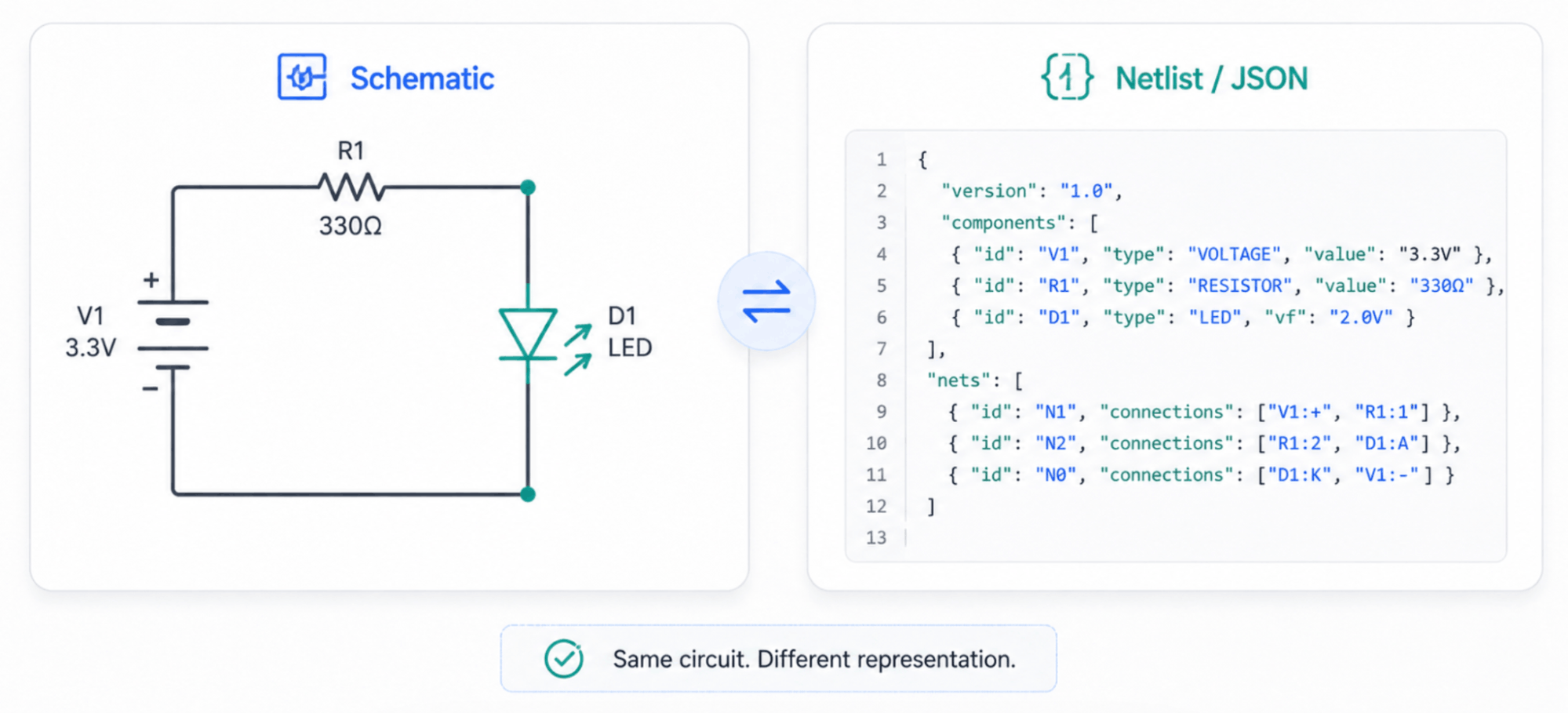
The public starter exports JSON containing components and pin-to-pin topology. Mapping that JSON into a specific target such as Altium, KiCad or OrCAD X is a project integration, not a one-click built-in export.
Where schematic capture sits in PCB design
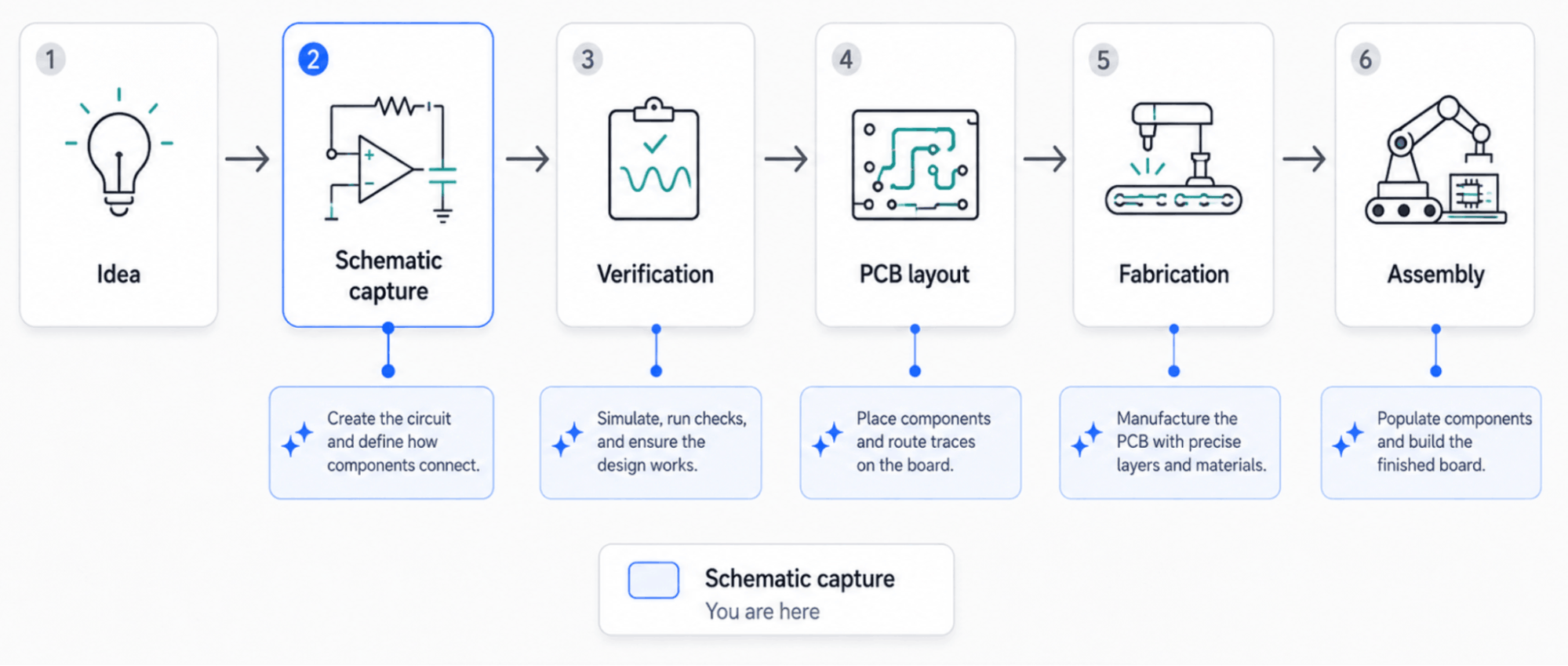
A modern electronics workflow is more detailed than "schematic, then layout." A useful sequence is:
- requirements
- architecture
- part selection, including footprint and library binding
- schematic capture
- annotation and ERC
- simulation, where the design is analog or mixed-signal
- netlist and schematic-to-layout transfer
- stackup and constraint definition
- placement
- routing
- DRC and DFM
- manufacturing outputs
- release
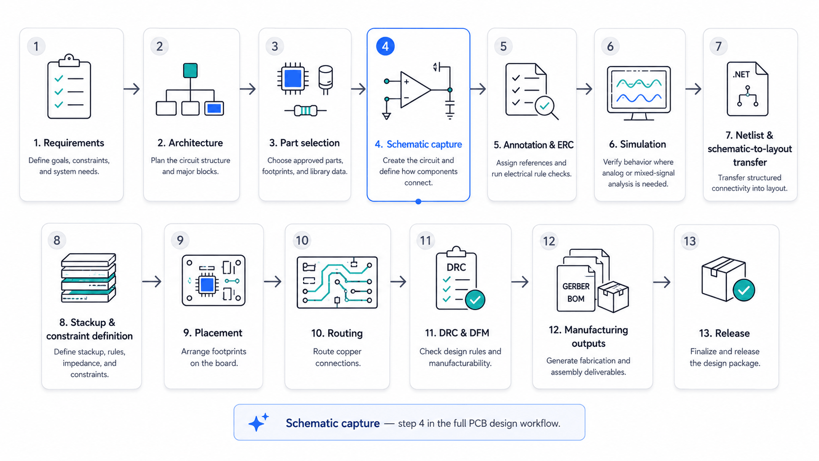
A schematic can exist before a footprint has been selected, although database-driven flows increasingly bind footprint data during part selection. The key boundary is still clear: schematic capture defines connectivity and constraints; PCB layout realizes that connectivity in physical copper.
Schematic capture vs PCB layout
| Area | Schematic capture | PCB layout |
|---|---|---|
| Main purpose | Define electrical connectivity and constraints | Realize that connectivity in copper while meeting signal integrity, power integrity, EMC and manufacturing limits |
| Main objects | Symbols, pins, wires, nets, net labels, power symbols, buses, sheet ports and junctions | Footprints, pads, traces, vias, layers, planes and pours, keepouts, stackup, mask and paste, silkscreen and drill data |
| Main question | What connects to what, and under which constraints? | How will that connectivity be physically implemented on the board? |
| Typical checks | ERC, connectivity compare and simulation | DRC, DFM, impedance and signal-integrity analysis |
| Output | Netlist and BOM, plus a schematic PDF in many workflows | Gerber X2 or IPC-2581 / ODB++, drill files, pick-and-place data, fab drawings and assembly drawings |
| Constraints | Net classes, differential pairs, impedance targets and DNP or variant flags are defined here | Constraints are carried into layout and enforced in copper and physical geometry |
The current Synergy Codes circuit offer deliberately stops before full board engineering. Simulation, electrical validation, footprint generation, PCB placement, copper routing and manufacturing files stay in specialist EDA.
Schematic capture vs a circuit drawing
A drawing can look like a circuit without carrying circuit structure. A captured schematic knows which pins connect, which components exist and which data belongs to them. That difference becomes visible as soon as the system has to run ERC, generate or compare a netlist, keep topology stable while geometry changes, connect to a product catalog or feed another engineering system.
A vector canvas gives users shapes. An engineering editor gives those shapes domain meaning. The implementation details behind pins, nets, junctions and routing are covered separately in Web-based schematic editor: the hard parts.
Download the electrical schematics checklist before your next design review
Get the checklistDesktop suites and browser-native schematic tools
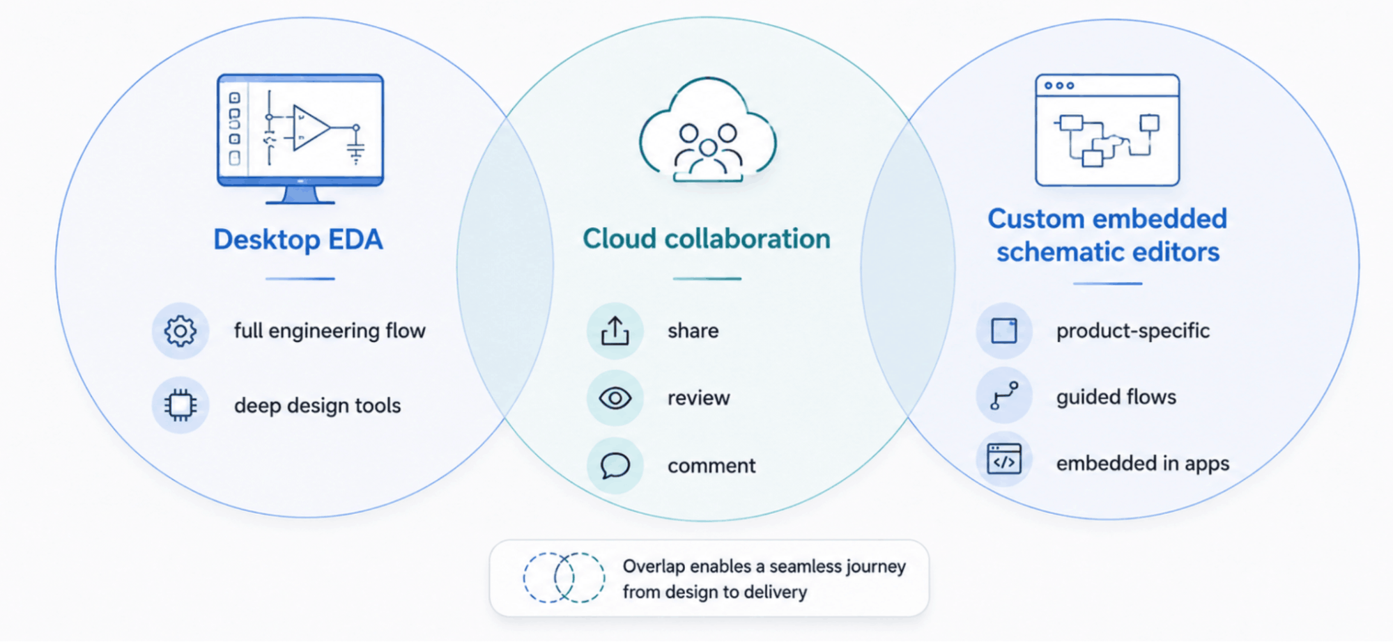
Desktop EDA remains the reference point for broad electronics workflows, while browser products prove that meaningful parts of the flow can live on the web.
KiCad
KiCad combines schematic capture and PCB layout in an open-source suite. Its schematic environment includes ERC, structured connectivity export and ngspice integration, so it covers far more of the engineering flow than a customer-facing concept editor.
Altium Designer and Altium 365
Altium Designer combines schematic capture, component management, PCB design and engineering collaboration. Altium 365 adds cloud and browser collaboration around that workflow. Browser access to electronics projects is therefore not new; the question is what kind of browser experience a company wants to own.
OrCAD X (Cadence)
OrCAD X is a Cadence product family. OrCAD X Capture CIS connects schematic entry with component data, dynamic ERC and mixed-signal simulation capabilities, then feeds the broader Cadence physical-design flow.
EasyEDA
EasyEDA is browser-native and tied closely to the JLCPCB / LCSC ecosystem, including a large component library, ordering workflow, imports from other EDA formats and SPICE-oriented simulation. It already proves that customers will design electronics in a browser.
Flux.ai
Flux.ai belongs in the browser-native category rather than the established desktop-suite bucket. It combines collaborative schematic editing, PCB design and AI assistance in a browser environment.
As of August 2026, another migration trigger is the end of Autodesk EAGLE support in June 2026, which gives teams a concrete reason to reassess where schematic capture and collaboration should live.
EasyEDA already proves customers will design in a browser. What it cannot do is restrict the canvas to one vendor's approved parts, enforce that vendor's compatibility rules and live inside that vendor's own product pages and quoting flow. That is the custom-product gap.
Why a company builds schematic capture into the browser
A component vendor may want a customer to create an initial concept before opening KiCad, Altium or OrCAD X. The browser interface can present an approved catalog, guided placement and company-specific compatibility rules, then save the concept and move the user into a sample, quote or engineering handoff.
A production example makes the idea less abstract. Synergy Codes has delivered a browser configurator for a lighting-fixture manufacturer where customers design from the manufacturer's catalog, power-group rules are enforced automatically and the result can produce an order-ready BOM and branded PDF. That is a custom application capability, not a feature claim about the public ngDiagram starter.
Synergy Codes documents the lighting-fixture configurator in the proof section of its custom circuit design software page. You can also open the live ngDiagram circuit demo to inspect the public starter in the browser.
The commercial value is not "schematics in a browser" by itself. It is the ability to make the design experience part of product discovery, quoting and customer handoff while keeping the full engineering stack downstream.
What ngDiagram provides underneath
ngDiagram is Synergy Codes' Apache 2.0-licensed Angular diagramming engine for interactive node-and-edge applications. The ngDiagram electric-circuit starter adds circuit-specific interaction on top of that engine: stable pin-to-pin connections, wire-to-wire branching, junction cleanup after deletion, orthogonal routing with manual reshaping, grid snapping, a small public component catalog and JSON topology export.
The public starter does not include undo/redo, keyboard navigation, ERC, simulation, footprint generation, PCB placement, copper routing, BOM/CSV export or direct export into Altium, KiCad or OrCAD X. Those boundaries matter because they separate a credible concept-stage foundation from a claim to replace professional EDA.
The canvas layer is Apache 2.0 licensed. Synergy Codes states that clients own the custom product code built for their implementation, without a per-seat license on the custom canvas layer, and self-hosting is available when required by the project.
The public repository exposes the starter code for inspection.
What stays in the EDA tool
The browser editor can cover concepting, controlled part selection and schematic topology. Detailed simulation, electrical correctness validation, footprints, physical placement, copper routing and manufacturing outputs remain in specialist EDA. For the AI side of the same boundary, see AI in PCB and circuit design: what's real, what's hype.
- What is schematic capture?
Schematic capture creates a structured logical model of an electronic circuit using component symbols, pins, nets and design constraints. Its connectivity can be represented as a netlist that downstream engineering tools can read and compare.
- Is schematic capture the same as PCB layout?
No. Schematic capture defines electrical connectivity and constraints. PCB layout realizes those relationships as physical component placement, copper, vias, layers and manufacturing geometry while meeting signal, power, EMC and fabrication limits.
- Can schematic capture work in a browser?
Yes. EasyEDA and Flux.ai already show that substantial electronics-design workflows can run in a browser. A custom browser editor has a different purpose when it must be embedded into one company's product, catalog, rules and commercial flow.
- What is ngDiagram?
ngDiagram is Synergy Codes' Apache 2.0-licensed Angular diagramming engine for interactive node-and-edge applications. The electric-circuit starter adds circuit-specific interaction while the full engineering stages remain in dedicated EDA.
- Does Synergy Codes replace Altium, KiCad or OrCAD X?
No. The current circuit-design offer focuses on concepting, controlled component selection and schematic topology. Simulation, ERC-grade electrical validation, footprints, PCB layout and manufacturing outputs remain in specialist EDA systems.
As the founder and CEO of Synergy Codes, Maciej guides Fortune 500 companies and startups in identifying how custom diagramming solutions can transform their operations. With 15+ years in the field, he leads a team of experts who've delivered 170+ implementations across diverse industries, streamlining workflows and enhancing decision-making.

Find how we can help you enhance your software and win more deals
Contact us to discuss your project. After you submit the form, we’ll get in touch with you within 48 hours to arrange a call.